


DocID13284 Rev 2
363/564
UM0404
XBUS pulse width modulation module
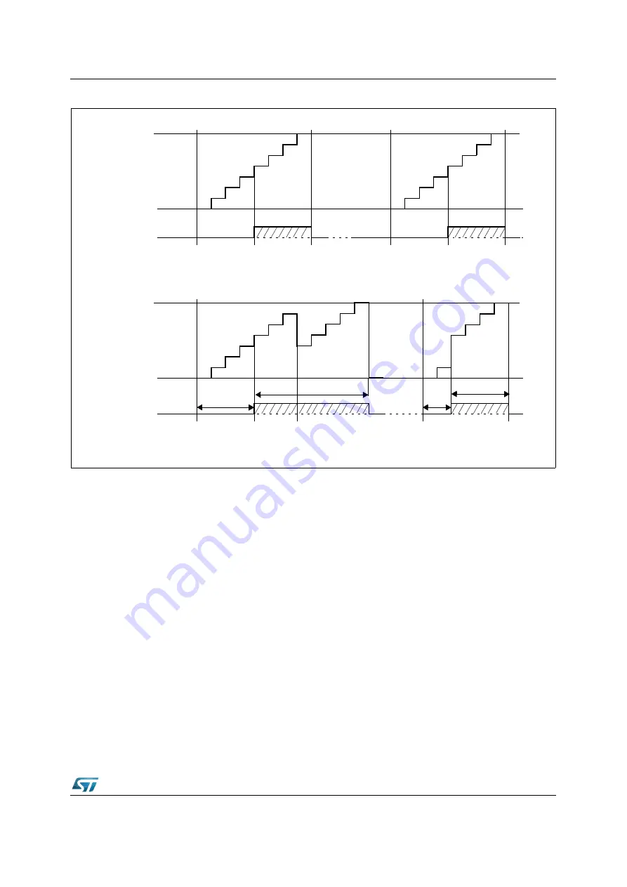
Figure 156. Operation and output waveform in single shot mode
After starting the timer (with PTRx = ‘1’) the output pulse may be modified via software.
Writing to timer XPTx changes the positive and/or negative edge of the output signal,
depending on whether the pulse has already started (the output is high) or not (the output is
still low). This (multiple) re-triggering is always possible while the timer is running, after the
pulse has started and before the timer is stopped.
Loading counter XPTx directly with the value in the respective XPPx shadow register will
abort the current PWM pulse upon the next clock pulse (counter is cleared and stopped by
hardware).
By setting the period (XPPx), the timer start value (XPTx) and the pulse width value (XPWx)
appropriately, the pulse width (t
W
) and the optional pulse delay (t
D
) may be varied in a wide
range (see
).
18.2 XPWM
module
registers
The XPWM module is controlled via two sets of registers. The waveforms are selected by
the channel specific registers XPTx (timer), XPPx (period) and XPWx (pulse width). Two
common registers control the operating modes and the general functions (XPWMCON0 and
XPWMCON1) of the XPWM module; the interrupt is controlled through the XBUS interrupt
circuitry (X-Peripherals interrupt line sharing concept).
7
6
5
3
4
2
1
0
XPPx
Period=7
XPTx Count
Value
XPWx Pulse
Width=4
Set PTRx
by Software
PTRx Reset
by Hardware
XPTx stopped
7
6
5
3
4
2
1
0
Set PTRx
by Software
LSR
for Next Pulse
6
5
3
4
2
1
0
XPPx
Period=7
XPTx Count
Value
XPWx Pulse
Width=4
7
6
5
4
t
D
Retrigger after
Write XPWx value to XPTx
1
0
7
6
5
4
t
D
Trigger before Pulse has started :
Write XPWx value to XPTx;
LSR
t
W
t
W
Shortens Delay Time t
D
Pulse has started :