27
Communication (page 27) below.
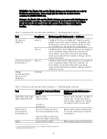
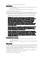
Suboptimal RF Communication
The Merlin™ PCS indicates the quality of the RF communication by the telemetry strength
indicator LEDs on both the programmer and the Merlin™ Antenna. Below is a list of potential
causes of suboptimal radio communication:
Possible Causes
The Merlin™ Antenna orientation/location is suboptimal.
People or objects interfere with the communication between the Merlin Antenna and the
device.
The Merlin Antenna is too far away from the device.
Someone is holding the Merlin Antenna.
Other products in the vicinity are causing electromagnetic interference (EMI).
The Merlin Antenna cable is wound around the Merlin Antenna.
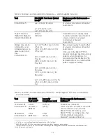
Solutions
Try to optimize RF communication (increase the number of telemetry strength indicator LEDs):
Move or reorient the Merlin™ Antenna slightly.
Make sure that the space between the Merlin Antenna and the device is free from interfering
objects/people.
Move the Merlin Antenna closer to the device.
Make sure that the front of the Merlin Antenna faces the implantable device.
Power off or remove equipment that could cause EMI.
Make sure the Merlin Antenna cable is not wound around the Merlin Antenna.
Do not hold the Merlin Antenna.
If none of the above solutions solve the problem, avoid using RF communication and use the
inductive telemetry wand instead.
Transportation
To move the Merlin™ PCS:
1.
Make sure that all disk activity has stopped (the hard disk becomes silent).
2.
Turn off the Merlin PCS.
3.
Disconnect the external devices.
4.
Disconnect the power cord.
5.
Close the display. Make sure that the cover latch is closed.
6.
Store the wand, Merlin™ Antenna, and ECG cables in the storage compartment or the
pouch. Carefully wind the cables to avoid damage.
CAUTION: To avoid breakage, do not lift the Merlin PCS by its display or by the
storage compartment lid.
Содержание Merlin 3638
Страница 4: ......
Страница 6: ......
Страница 7: ...3 Features Figure 1 Merlin Patient Care System ...
Страница 10: ......
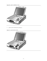
Страница 25: ...21 Figure 18 Open the USB port cover 3 Insert the Wi Fi USB into the USB port Figure 19 Insert the Wi Fi USB ...
Страница 32: ......
Страница 47: ......
Страница 48: ......
Страница 49: ......


