background image

11. GREEN SYSTEM SETUP INSPECTION CHECKLIST

Item

Inspection

Ensure that all cables are connected properly and that
connections are secure. Make a check mark in the box
(right) to indicate completed tasks.

Status

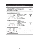
Item 1. Is the power supply of all units on?

Note that the arrow indicates
the location of the power
switch.
1 — On – LED is lit.
0 — Off – LED is not lit.

Note that the arrow
indicates the location of the
power switch.
1 — On – LED is lit.
0 — Off – LED is not lit.

Note that the arrow indicates
the location of the power
switch.
1 — On – LED is lit
0 — Off – LED is not lit.

Completed

Completed

Completed

61

Содержание G572U

Страница 1: ...2011 12 G572U BIKE ...

Страница 2: ...nnections STEP 14 Seat Height Adjustment STEP 15 Seat Height AdjustmentAdjustment STEP 16 Integrated TV Installation STEP 17 How to Set the Number of Fitness Products per Pod 5 UNDERSTANDING THE G572U DISPLAY CONSOLE DISPLAY Specifications DISPLAY Overview DISPLAY Windows DISPLAY Keys DISPLAY Screens 6 OPERATING THE G572U EXERCISE BIKE OPERATION Quick Start OPERATION Workout Program Setup OPERATIO...

Страница 3: ...CISE 9 MAINTENANCE MAINTENANCE Messages MAINTENANCE Disconnecting the Boost Converter Box MAINTENANCE Chart MAINTENANCE Checklist MAINTENANCE One Year Maintenance Log 10 BLOCK DIAGRAM 11 GREEN SYSTEM SETUP INSPECTION CHECKLIST 12 GREEN SYSTEM CABLE CONNECTION ILLUSTRATION 54 54 54 55 56 57 58 59 60 61 65 ...

Страница 4: ...ned for years of reliable usage this product was made to become an integral part of your commercial fitness venue Before this product is assembled or operated we recommend that you familiarize yourself with this manual Understanding the correct assembly and operation of this product will help ensure that exercisers obtain their fitness goals safely and successfully 1 1 INTRODUCTION ...

Страница 5: ...2 2 IMPORTANT SAFETY PRECAUTIONS Such parts ...

Страница 6: ...3 If you are a French speaking person in North America please place the sticker contained in the owner s manual on the product as shown Customers in other areas will not receive the sticker ...

Страница 7: ...4 a ...

Страница 8: ...une personne de langue française en Amérique du Nord s il vous plaît placer l autocollant figurant dans le manuel du propriétaire sur le produit comme indiqué Les clients dans d autres pays ne recevront pas l autocollant ...

Страница 9: ...A1 A2 A3 A4 A5 A6 1 1 Assembly Parts A7 A8 6 1 1 1 1 1 1 3 LIST OF PARTS Pedestal and display Bottle holder Main frame and body Pedal set Rear support Seat bottom Hardware kit Boost converter box Boost converter connector cable A9 1 ...

Страница 10: ...ndle Screwdriver bit M5 M6 12 15 green Flat and Phillips No Name 21 22 23 24 25 Parts on the Product Specification Notes Inner hex screw Serrated washer Cushion washer Hex nut Flat washer Mushroom top inner hex screw Beveled head Phillips screw Mushroom top inner hex screw and washer M8 L20 M8 L25 D18 d8 5 t2 0 D13 0 25 0 35 M8 D20 d8 t1 0 M5 P0 8 L25 M6 P1 0 L10 ψ ...

Страница 11: ...ising on the product For brevity the word screws is used where screws washers and other hardware may be involved Remove packaging as shown to leave the product on a flat piece of cardboard Remove bike parts Set them aside in a safe place Cut the corners of the box to leave the main frame and body alone on a flat piece of cardboard pedals etc before discarding the packaging material left and right ...

Страница 12: ...rt a Remove screws 21 from the rear support b Insert the stem of the rear support A5 into the rear tube of the main frame A3 Align the holes in both pieces c Install the screws 21 that had been removed from the rear support First secure screws in area A then secure screws in area B 9 c b a ...

Страница 13: ...nstall the Bottle Holder Please follow steps a through b below to install the bottle holder a First remove screws 24 from the pedestal A1 b Use these screws 24 to secure the bottle holder A2 onto the pedestal b a ...

Страница 14: ...of the way Insert the pedestal assembly A1 into the mount piece on the main body A3 Use screws 22 to secure the pedestal assembly A1 into the mount piece on the main body From the hardware kit remove the soft caps Insert caps 10 onto the screws Note If you are installing an integrated TV module after removing screws in step a refer to step 12 in this manual Then after completing TV installation ca...

Страница 15: ...main frame Then use screws 23 to secure the seat bottom A6 to the main frame c Note that pedals A4 are marked either L for left or R for right Each pedal must be installed on the appropriate side The stem of the right pedal screws in clockwise The stem of the left pedal screws in counterclockwise Start securing pedals by hand to ensure proper threading Then use the wrench to fully secure the pedal...

Страница 16: ...13 STEP 6 Move the Product Lift the rear support and push rolling the bike into place for use c a b ...

Страница 17: ... down on the legs of the rear support Does the bike sit flat on the floor or does it rock If necessary follow steps a through c to level the bike a First loosen the leveler nuts b Adjust the leveler foot downward until it touches the floor c Secure the leveler nut against the frame of the product c b a ...

Страница 18: ...STEP 8 Install the Boost Converter Box 15 ...

Страница 19: ...il the metal plates contact each other securely boost converter box Connect boost converter A8 cables to the power switch bracket connectors in area A B In area A connect cables in order and rotate the connectors to secure the connection Note To ensure a good connection listen for the click sound and rotate the connector until it stops rotating In making the connection make sure that the empty not...

Страница 20: ...he boost converter box the boost converter box Remove connector covers on the sides of A8 Insert the between unit connection cable A9 into the connector on Then use screws to secure the connection Only connect up to ten products per inverter On the last unit in a line of fitness products leave the connector cover in place on the side with no cable connection 17 ...

Страница 21: ...er switches on the inverter and the fitness products are in the OFF position Connect the DC power cord from the inverter to boost converter Use screws to secure the power cord into place the left hand terminal on the first 18 STEP 10 Connect Inverter ...

Страница 22: ...The illustration below shows Green System power cord connections fitness products to boost converters the inverter to the electrical panel power grid 19 STEP 11 Green System Connections ...

Страница 23: ...he assembly and complete the connections Connections must comply with electrical regulations STEP 13 Confirm Proper Installation and Cord Connections a Confirm that the inverter is installed properly Confirm that the inverter is connected properly to the electrical panel b Confirm that the inverter and the boost converter are connected properly Confirm that each boost converter is connected to its...

Страница 24: ...e and Aft Adjustment a Push the seat adjustment lever down to loosen the seat b Push the seat to a suitable position toward the front or toward the back of the unit Then lift the lever up to secure the seat into place b a ...

Страница 25: ...ment 22 a To adjust the seat upward simply pull the seat upward b To adjust the seat downward lift the seat adjustment knob and push the seat downward to a suitable position Then release the knob to secure the seat in place b a ...

Страница 26: ...ted TV module please skip this step a First remove screws from the back of the display b Disconnect wires in areas A B and C Remove the two wires in area D The two wires in area D will not be needed for use with the integrated TV module Note If you are installing an integrated TV module after removing screws in step a refer to steps 12 in this manual b a A B C D ...

Страница 27: ...ds upward and thread them through the pedestal and out through the display back Then remove the plastic cover over the connector ends After completing these two steps refer to the standard integrated TV screen installation instructions to complete the integrated TV installation process Continue the installation process referring to page 11 through 15 of the integrated TV installation manual b a 24...

Страница 28: ...s in the pod has been established At setup follow the steps below to enter into each fitness product the number of units in the pod 1 Simultaneously press and hold WORKOUT LEVEL WORKOUT LEVEL CHANGE DISPLAY keys for two seconds This activates the passcode setting mode 2 The message screen will show PASSWORD 0000 The passcode 8250 must be entered before the number of units in the pod can be entered...

Страница 29: ...meric keys 0 through 9 to input the number of products in the pod b If desired press the CLEAR key to reset all values to zero c After the correct number of units in the pod has been entered press the ENTER key to commit the number to the product memory After the ENTER key has been pressed the units per pod setting mode will end d If desired press the STOP key at any time to exit this mode and to ...

Страница 30: ... test cardio weight loss interval plateau fat burn custom heart rate Heart rate range 40 250 beats per second RPM Rotations Per Minute 5 150 Watts 0 9999 DISPLAY Specifications The G572U exercise cycle is designed for user convenience With better feedback about your workout you get better results The following explains the display key and window functions Please read this manual understand the dis...

Страница 31: ...ys Exercise Feedback Screen Level Screen Workout Program Keys Setting Keys Dot Matrix Screen Output Possible Output 100 Power Output Setting Screen window The GREEN ENERGY OUTPUT RATIO window shows alternator output ratio The power output setting window shows setting values exercise goals and power output in watts ...

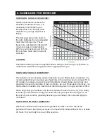
Страница 32: ...e settings to 0 This key allows you to directly control resistance via resistance keys This workout program might well be called Choose from one to 20 stages each with an increasing level of difficulty This workout program gradually increases in difficulty plateaus then tapers off in a 20 60 20 pattern Press this key to select one of an almost endless number of randomly generated workout programs ...

Страница 33: ...and display the ACCU DATA While in ACCU DATA displaying mode press STOP PAUSE HOLD TO RESET key to display accumulative energy generated Afterwards press STOP PAUSE HOLD TO RESET key to return to BANNER SELECT PROGRAM screen Press hold STOP PAUSE HOLD TO RESET key for 2 seconds will reset the console and return to BANNER screen Press this key to activate the fan There are four settings off low med...

Страница 34: ... column Please see the illustration below The completed portion of the workout is represented by the red columns The active part of the workout is represented by the green column The remaining portion of the workout is represented by the orange dots When someone pedals on the cycle the top green LED flashes see the arrow When no one pedals the green column remains lit This screen shows workout fee...

Страница 35: ...t feedback changes every six seconds If no one pedals for six seconds the following message will appear in the workout feedback screen This screen shows alternator power output as a percentage of the maximum power output actual power output in watts maximum power output possible in watts 100 Note that the maximum power output for a particular product is determined via software at setup GREEN ENERG...

Страница 36: ...ablish a workout goal and user age and weight If you activate the bike by pressing the QUICK START key and then select a workout program original workout feedback values are carried over to the new workout Unlike QUICK START workout programs require the user to select a goal either time distance or calories and to input values for age and weight Age values are used to calculate target heart rates ...

Страница 37: ...hen keys in the setting area are held down time values change by one digit every 0 2 seconds When using numeric keys 0 9 digit placement is determined as shown in the following example Press 3 The setting window will show the following Press 4 The setting window will show the following Press 5 The setting window will show the following To return to the first step while the minute value flashes pre...

Страница 38: ...for six seconds the following appears on the message screen for two seconds When keys in the setting area are pressed briefly distance values change by 0 25 mile or 0 4 kilometers depending on the distance unit setting If keys in the setting area are held down for one second time values change by 0 25 mile or 0 4 kilometers every 0 2 second When using numeric keys 0 9 and decimal keys digit placem...

Страница 39: ...r numeric keys 0 9 to select your calorie expenditure goal value Press the ENTER key to confirm your setting and proceed to the age setting Notes about the calorie setting appear below The calorie setting range is 100 to 9999 kcal with a default value of 100 kcal After calorie is selected as the workout goal the CALORIES key LED remains lit The setting window will show the default value of 100 The...

Страница 40: ...100 kcal and the following reminder will appear for two seconds in the Press the CLEAR key at any time to clear settings to 0 00 The decimal key does not operate during the time setting mode After establishing the workout goal ENTER AGE appears on the Use keys in the setting area or numeric keys 0 9 to select your age Press the ENTER key to confirm the age setting and proceed to the weight setting...

Страница 41: ...shows either lb or kg the default weight of 165 lb or 75 kg appears and ENTER WEIGHT KG or ENTER WEIGHT LB appears on the message screen depending on the unit setting Use keys in the setting area or numeric keys 0 9 to select your weight Press the ENTER key to confirm the weight setting and begin your workout Notes about the weight setting follow The weight setting range is from 50 to 500 lb 20 to...

Страница 42: ...range of 50 to 500 lb or 20 to 227 kg is exceeded one of the following messages appears for two seconds Press the CLEAR key at any time to clear settings to 0 The decimal key does not operate during the age setting mode Follow prompts to begin your workout Please refer to for specific information about workout programs The following explains features of the workout programs When the manual program...

Страница 43: ...stration Random programs are generated with the following conditions Any single workout illustration can only appear once in 20 samples Starting resistance can never be higher than level six The difference between the levels of two adjacent columns cannot exceed six levels The same level cannot recur for more than three columns There are 65535 variations from which illustrations are randomly gener...

Страница 44: ...15 seconds if the RPM is less than 45 RPM or more than 55 RPM At the end of the test END OF FIT TEST will appear on the exercise feedback screen followed by YOUR SCORE IS where represents a number from 0 to 90 with 90 being the maximum score possible In these heart rate control programs the resistance level and recommended RPM will automatically change to keep the exerciser s pulse at the optimum ...

Страница 45: ...the target heart rate by one or more for more than two seconds resistance decreases by one segment After making adjustments four times consecutively if actual heart rate is not less than the target heart rate no adjustments will occur for 15 seconds after which downward adjustments will occur every two seconds Adjustments will not fall below 12 segments LEVEL 3 Note Each resistance level occupies ...

Страница 46: ...into the display the message window will appear as follows At this time the workout goal percentage completed screen and the dot matrix screen will not be lit If no keys are pressed within six seconds the following prompt will appear for two seconds on the At this time press numerical keys 1 2 or 3 to select one of the three interval programs or directly press the ENTER key to choose the first int...

Страница 47: ...hanged at any time The resistance setting of the remaining part of the active segment will change Already completed segments will remain unchanged The first time that a rest segment transitions to a work segment Likewise the first time that a work segment transitions to a rest segment the display will beep once and the following message will appear for two seconds the following message will appear...

Страница 48: ...stance levels in this time based workout program gradually increase level off then gradually decrease The first and last segments of this workout each occupy 20 of the workout The middle segment occupies 60 of the workout In the first segment resistance increases from level one to level twelve The middle segment retains level twelve resistance In the last segment resistance drops from level twelve...

Страница 49: ...1 Stage 4 1 3 5 2 4 Stage 5 2 4 6 1 3 5 Stage 6 1 4 7 2 3 5 6 Stage 7 1 2 3 4 8 7 6 5 Stage 8 2 4 6 8 3 5 7 9 Stage 9 3 4 5 6 7 8 9 10 Stage 10 4 6 8 10 5 7 9 11 Stage 11 5 6 12 7 8 11 9 10 Stage 12 6 7 8 13 9 10 11 12 Stage 13 7 9 11 8 10 12 13 14 Stage 14 8 9 10 10 11 12 12 13 13 14 14 15 Stage 15 9 10 16 15 14 13 12 11 Stage 16 10 13 15 17 17 16 15 14 12 11 Stage 17 11 12 13 14 18 17 16 15 Stag...

Страница 50: ...ase the target heart rate Beat per minute values change by one beat each time keys are pressed To change values faster hold these keys down for more than one second Values will change by one beat per minute every 0 2 second Press the ENTER key to confirm your setting If you do not press the ENTER key within six seconds the message window will show PRESS ENTER If your entry exceeds the range of 84 ...

Страница 51: ...he setting value But if the lowest range value is lower than the actual value shown in the workout feedback display the original setting remains in effect If the new value is higher than the actual workout value and lower than the original setting the setting value decreases If the new value is higher than the actual workout value and higher than the original setting the setting value increases If...

Страница 52: ...s such as USB memory sticks iPod devices cameras mobile phones and other items Third generation or newer iPod devices support power charging via USB ports Note iPod is a trademark of Apple Inc registered in the US and other countries Made for iPod means that an electronic accessory has been designed to connect specifically to iPod and has been certified by the developer to meet Apple performance s...

Страница 53: ...O SELECT UNIT OR ENTER To exit the user preference selection mode press the STOP key The startup banner screen will appear The stop key can be used to exit the user preference mode at any time within this mode According to the speed unit setting total distance will appear as either DIST XXXXXX MILE or DIST XXXXXX KM where XXXXXX represents a number Press the ENTER key to view total time Notes abou...

Страница 54: ...y board version Or press the STOP key to exit this setting mode The display program version will appear as CTL XG572H 1A for example In this example the X represents the multiple language setting Press the ENTER key to view the drive board program version Notes about operating this product while the display program version is visible If no keys are pressed within six seconds PRESS ENTER will appea...

Страница 55: ...ving the heart rate value from an exerciser on one product appear on another product 5 Heart rate values are for comparison only Do not use them for medical treatment or other purposes Space fitness products apart by at least 39 inches 100 It is easy to use the contact heart rate mechanism Simply put both hands on the silver contact plates one per side and hold them there continuously As soon as y...

Страница 56: ...ate detection and signal transmission devices have been known to interfere with the operation of pacemakers possibly endangering human life If you have a pacemaker the use of such devices must be undertaken at your own risk We recommend that you conduct an exercise test under your doctor s supervision The purpose of the test would be to ensure the safety and reliability of the simultaneous use of ...

Страница 57: ...s on your fitness level In general it is recommended that you maintain your heart rate in the training zone for at least 15 to 20 minutes to realize an aerobic benefit Beginners should always start slowly and gradually increase the duration of their workouts As your fitness level improves you will be able to maintain your heart rate in the training zone for longer periods of time When beginning yo...

Страница 58: ...too hot resistance output is limited to 50 watts When the operating temperature cools resistance will again increase to 100 watts ERR1 This message indicates that the inverter is overloaded It can appear once every 30 seconds after a workout has begun At this time the fitness product can operate normally except for the resistance function There will be no resistance To remedy the situation turn of...

Страница 59: ... before detaching the from the fitness product First turn power off Detach the by following steps A through D Note the sequence of steps in which cables must be disconnected in steps C and D In step D first press area A upward to release the cable boost converter box boost converter box 1 2 ...

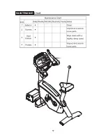
Страница 60: ...57 MAINTENANCE Chart ...

Страница 61: ...ecure them if necessary 1 On recumbent bikes apply silicone lubricant to the seat carriage rail Please follow standard safety precautions when working on this product Electronic components can carry an electrical charge even after the product has been turned off For safety turn off unit power Wait five minutes to allow capacitors to discharge Then disconnect the power cord from the wall socket if ...

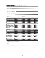
Страница 62: ...rior screws Seat back bottom Pedals Daily Tasks Week 5 Week 6 Week 7 Week 8 Exterior screws Seat back bottom Pedals Daily Tasks Week 9 Week 10 Week 11 Week 12 Exterior screws Seat back bottom Pedals Weekly Tasks Week 1 7 Week 8 14 Week 15 21 Week 22 28 Seat carriage Weekly Tasks Week 29 35 Week 35 42 Week 43 49 Week 50 52 Seat carriage applies to recumbent cycles only ...

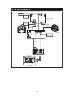
Страница 63: ...60 10 BLOCK DIAGRAM CN1 CN8 CN4 CN 7 CN5 CN3 CN6 CN9 CN2 ...

Страница 64: ...ted tasks Status Item 1 Is the power supply of all units on Note that the arrow indicates the location of the power switch 1 On LED is lit 0 Off LED is not lit Note that the arrow indicates the location of the power switch 1 On LED is lit 0 Off LED is not lit Note that the arrow indicates the location of the power switch 1 On LED is lit 0 Off LED is not lit Completed Completed Completed 61 ...

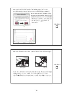
Страница 65: ...esistor mode can only be activated after the inverter has malfunctioned and the inverter bypass box is connected Completed Item 3 Is the boost converter power cable screwed in securely Insert the connector and rotate it clockwise as shown until it stops turning and you hear a click sound Only then can you be assured that there is no looseness and the connection is secure Completed 62 ...

Страница 66: ...connected Otherwise it will be very difficult to connect the cable On G572U R there is no such bracket but there is a metal protective cover at the top Since this cover protrudes only slightly it does not affect cable installation Item 4 Are cable connectors inserted fully and their screws tightened securely As shown insert the connectors fully and secure their screws Only after this is done can t...

Страница 67: ... for the number of fitness products in the pod Enter the procedure to establish the number of products in the pod Inspect whether this setting matches the actual number of products in the pod Item 6 Is the inverter setting correct Inspect the inverter setting Completed Completed 64 ...

Страница 68: ...12 GREEN SYSTEM CABLE CONNECTION ILLUSTRATION 65 Your Authorized SPORTS ART Distributor ...

Отзывы: