50
User Preferences and Part Versions
OPERATION
Units of measure shown on this product's display can be modified. Total operating
distance and hours of use can be viewed and deleted. Display and drive board
version numbers can also be viewed.
To accomplish any of these tasks, at the startup banner screen (as "G572" appears
on the screen), hold the ENTER key for three seconds. User preference mode will
be activated.
The display will show "UNIT-MPH" or "UNIT-KPH" depending on the original speed
unit setting. Press
/
keys to toggle between the two settings. When your
preference appears, press the ENTER key to make your selection and proceed to
view total distance.
Notes about unit settings:
If no keys are pressed within six seconds, the message screen will show the
message "PRESS UP/DN TO SELECT UNIT OR ENTER".
To exit the user preference selection mode, press the STOP key. The startup
banner screen will appear. (The stop key can be used to exit the user preference
mode at any time within this mode.)
According to the speed unit setting, total distance will appear as either "DIST
XXXXXX MILE" or "DIST XXXXXX KM", where XXXXXX represents a number.
Press the ENTER key to view total time.
Notes about operating the product while total distance is visible:
If no keys are pressed within six seconds, "PRESS ENTER" will appear on the
message screen for two seconds.
To clear total distance memory, press the CLEAR key for three seconds. "DIST-0
KM" - or "DIST-0 MILE" will appear, indicating the distance memory has been
erased.
To exit the user preference mode, press the STOP key. The startup banner screen
will appear.
Total time of use will appear as "TIME XXXXXX HOUR", where XXXXXX represents
a number. Press the ENTER key to view the display program version.
UNITS
TOTAL DISTANCE
TOTAL TIME
<
>
▲ ▼
˙
˙
˙
˙
˙
Содержание G572U
Страница 1: ...2011 12 G572U BIKE ...
Страница 5: ...2 2 IMPORTANT SAFETY PRECAUTIONS Such parts ...
Страница 7: ...4 a ...
Страница 16: ...13 STEP 6 Move the Product Lift the rear support and push rolling the bike into place for use c a b ...
Страница 18: ...STEP 8 Install the Boost Converter Box 15 ...
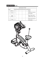
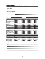
Страница 60: ...57 MAINTENANCE Chart ...
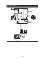
Страница 63: ...60 10 BLOCK DIAGRAM CN1 CN8 CN4 CN 7 CN5 CN3 CN6 CN9 CN2 ...
Страница 68: ...12 GREEN SYSTEM CABLE CONNECTION ILLUSTRATION 65 Your Authorized SPORTS ART Distributor ...


