


Z100080
ZX-
1 Operator’s Manual
Spinergy/SMP
Page 19
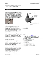
2. Remove cover
2.
Remove rear gas spring bolt.
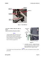
3.
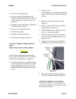
Reposition anti-tilt height adjustment
bracket so that anti-tilt wheels are between
1 and 2 inches below backrest spacer bar
(Figure 7).
4.
Install two nuts and washers securing anti-
tilt height bracket (Figure 7).
5.
Remove two anti-tilt shock nuts.
6. Re-install gas spring.
7. Install two anti-tilt shock nuts.
8. Perform anti-tilt width adjustment.
ANTI-TILT WHEEL WIDTH ADJUST-
MENT
Adjust anti-tilt wheels width as follows:
CAUTION
Anti-tilt wheel width adjustment procedure
must be performed before ZX-1 use. Failure to
comply may cause damage to equipment.
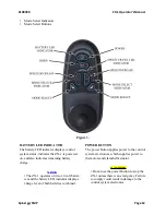
1.
Completely open ZX-1 clamshell/actuator
by selecting mode select button on control
panel and pushing joystick forward until
clamshell/actuator completely opens (Fig-
ure 3).
•
It will help to have left and right armrests
removed during anti-tilt wheels width posi-
tioning.
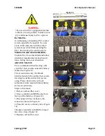
3.
Remove four cross member allen bolts.
(Figure 9).
4.
Remove spacer bar by removing bolts at
each end of bar (Figure 10).
5.
Widen adjustable cross member as neces-
sary to fit width of wheelchair.
6.
Manually back wheelchair centered into
ZX-1 base with clamshell/actuator still in
open position.
7.
Align ZX-1 anti-tilt wheels with wheel-
chair backrest vertical posts (Figure 11).
Figure 11.
8.
Once desired width is achieved, tighten
four cross member allen bolts (Figure 8).
JOYSTICK MODULE PLACEMENT
The joystick module comes pre installed on
right armrest, but may be configured on either
the left or right armrest.


