-54-
For Machines Mfg. Since 8/11
Model SB1001 8K
™
Lathe
S E R V I C E
Gib Adjustment
The goal of adjusting the gib screws is to remove
sloppiness or "play" from the ways without over-
adjusting them to the point where they become
stiff and difficult to move.
In general, loose gibs cause poor finishes and
tool chatter; however, over-tightened gibs cause
premature wear and make it difficult to turn the
handwheels.
The gib adjustment process usually requires
some trial-and-error. Repeat the adjustment
process as necessary until you find the best
balance between loose and stiff movement. Most
machinists find that the ideal gib adjustment is
one where a small amount of drag or resistance
is present, yet the handwheels are still easy to
move.
Before you begin adjusting the gibs, make sure
the ways are free of chips and grime, and they
are well lubricated so they can move smoothly
and without interference.
Saddle Gib
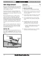
The saddle gib is located underneath the rear of
the saddle (see Figure 89). This gib is a flat bar
that is sandwiched between the gib plate and the
bedway.
Tools Needed
Qty
Wrench 8mm .........................................................1
Hex Wrench 2.5mm ..............................................1
To adjust the saddle gib:
1.
DISCONNECT LATHE FROM POWER!
2.
Make sure the carriage lock is loose and the
half nut is disengaged so that the carriage
can move freely.
3.
Loosen the hex nuts on the gib screws, then
loosen the gib screws two or three turns.
4.
Use the handwheel to move the carriage
back and forth—this will ensure the gib is
loose.
5.
Re-tighten the gibs screw evenly until
a slight resistance is felt, then use the
handwheel to test carriage movement.
— Loosen or tighten the gib screws evenly
until you are satisfied with the gib
adjustment.
6.
Without moving the gib screws, re-tighten
the hex nuts to secure the settings.
Figure 89. Saddle gib components.
Gib
Gib Plate
Gib Screws

