1-3
16
US
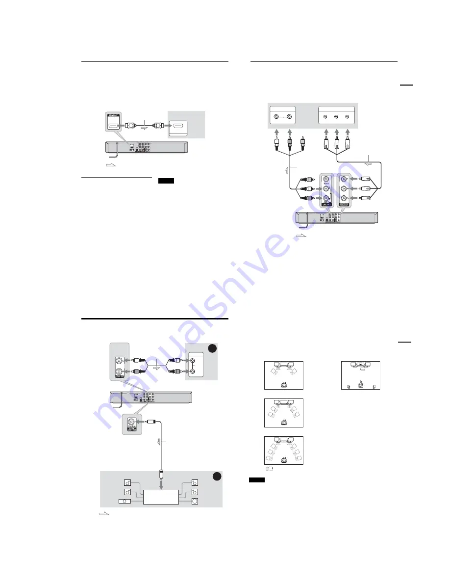
If your TV has an HDMI input jack
Connect the HDMI* OUT jack using a certified Sony HDMI cord (not supplied). You will enjoy high
quality picture and sound. If your TV accepts progressive 1080p format signals, you must use this
connection. The HDMI indicator is lit in the front panel display when the recorder outputs signals through
the HDMI OUT jack.
Be sure to turn off the recorder before connecting an HDMI cord.
* This DVD recorder incorporates High-Definition Multimedia Interface (HDMI™) technology. HDMI, the HDMI
Logo and High-Definition Multimedia Interface are trademarks or registered trademarks of HDMI Licensing LLC.
Using the Control for HDMI
functions for ‘BRAVIA’ Sync (for
HDMI connections only)
By connecting Sony components that are
compatible with the Control for HDMI function
with an HDMI cord (not supplied), operation is
simplified as below:
• One-Touch Play (page 38)
• System Power-Off
When you turn the TV off by using the
"
/
1
button on the TV’s remote, the components
compatible with the Control for HDMI function
turn off automatically.
To prepare for the ‘BRAVIA’ Sync features
Set “Control for HDMI” to “On” in the “Features”
setup (page 85). For details on TV settings, refer
to the operating instructions supplied with the TV.
Notes
• You cannot connect the HDMI OUT jack to DVI jacks
that are not HDCP compliant (e.g., DVI jacks on PC
displays).
• Depending on the connected component, the Control
for HDMI function may not work. Refer to the
operating instructions supplied with the component.
• The recorder supports only the playback option of
Control for HDMI. “Player” appears on the TV screen
when using the Control for HDMI functions.
HDMI IN
TV or
projector
HDMI cord (not supplied)
to HDMI OUT
: Signal flow
DVD recorder
to HDMI input
H
ook
ups
and
Se
tti
n
gs
17
US
If your TV has component video input jacks
Connect the COMPONENT VIDEO OUT jacks using a component video cord (not supplied) or three
video cords (not supplied) of the same kind and length. You will enjoy accurate color reproduction and
high quality images.
If your TV accepts progressive 480p format signals, you must use this connection and then set
“Progressive” of “Video” to “On” in the “Setup” display (page 81). The PROGRESSIVE indicator lights
up when the recorder outputs progressive signals.
When using this connection, be sure to connect the audio cord to the LINE OUT (AUDIO L/R) jacks.
COMPONENT VIDEO IN
P
B
P
R
Y
AUDIO
L
R
INPUT
: Signal flow
TV or projector
(red)
(white) (green)
Component video cord
(not supplied)
(red)
(blue)
(red)
(green)
(blue)
to COMPONENT
VIDEO OUT
Audio/video cord
(supplied)
(white)
(red)
to LINE OUT
(AUDIO L/R)
DVD recorder
18
US
Step 4: Connecting to Your AV Amplifier (Receiver)
Select one of the following patterns
A
or
B
, according to the input jack on your AV amplifier (receiver).
This will enable you to listen to sound through your AV amplifier (receiver).
AUDIO
INPUT
L
R
B
A
: Signal flow
AV amplifier (receiver)
(red)
(white)
Audio cord
(not supplied)
(white)
(red)
DVD recorder
to AUDIO OUT (L/R)
to DIGITAL AUDIO OUT
(COAXIAL)
Coaxial digital cord
(not supplied)
[Speakers]
Rear (L)
Front (L)
Center
to coaxial digital
input
[Speakers]
Rear (R)
Front (R)
Subwoofer
AV amplifier (receiver)
with a decoder
H
ook
ups
and
Se
tti
n
gs
19
US
A
Connecting to audio L/R jacks
This connection uses a stereo amplifier’s
(receiver’s) two front speakers for sound.
You can enjoy the surround function that creates
virtual speakers from two stereo speakers. Select
“Surround1,” “Surround2,” or “Surround3” in
“Surround” of the “Audio” setup (page 83).
Surround 1
Surround 2
Surround 3
Note
Make sure that your listening position is between and at
an equal distance from your speakers, and that the
speakers are located in similar surroundings.
B
Connecting to a digital audio input jack
Use this connection if your AV amplifier
(receiver) has a Dolby
*1
Digital or DTS
*2
decoder
and a digital input jack. You can enjoy the
surround effect of Dolby Digital (5.1ch) or DTS
(5.1ch).
After you have completed the connection, make
the appropriate settings under the “Audio” setup
(page 82). Otherwise, no sound or a loud noise
will come from your speakers.
*1
Manufactured under license from Dolby Laboratories.
“Dolby” and the double-D symbol are trademarks of
Dolby Laboratories.
*2
Manufactured under license under U.S. Patent #:
5,451,942 & other U.S. and worldwide patents issued
& pending. DTS and DTS Digital Out are registered
trademarks and the DTS logos and Symbol are
trademarks of DTS, Inc. © 1996-2007 DTS, Inc. All
Rights Reserved.
z
Hints
• For correct speaker location, see the operating
instructions supplied with the connected components.
• With a coaxial digital connection, you cannot:
– use the virtual surround effects of this recorder.
– switch the bilingual sounds on a DVD-RW/DVD-R
(VR mode) by pressing AUDIO when you set “Dolby
Digital” to “Dolby Digital” in the “Audio” setup
(page 82).
Virtual speaker
Содержание RDR-GX360
Страница 36: ...2 3E DVD MAIN BOARD FRONT BOARD JACK BOARD Fig 2 4 Circuit Board Locations 2 2 CIRCUIT BOARD LOCATIONS ...
Страница 39: ...4 1 DVD Main PCB 4 4 4 3 COMPONENT SIDE ...
Страница 40: ...4 6 4 5 CONDUCTOR SIDE ...
Страница 41: ...4 8 4 7 4 2 Jack PCB COMPONENT SIDE ...
Страница 42: ...4 10 4 9 CONDUCTOR SIDE ...
Страница 43: ...4 12 4 11 4 3 Function PCB COMPONENT SIDE CONDUCTOR SIDE ...
Страница 44: ...4 14E 4 13 4 4 Front PCB COMPONENT SIDE CONDUCTOR SIDE ...
Страница 46: ...5 4 5 3 5 1 S M P S Jack PCB ...
Страница 47: ...5 6 5 5 5 2 Power Jack PCB ...
Страница 48: ...5 8 5 7 5 3 AV Decoder DVD Main PCB ...
Страница 49: ...5 10 5 9 5 4 AV Link TS in_Out DVD Main PCB ...
Страница 50: ...5 12 5 11 5 5 Connector DVD Main PCB ...
Страница 51: ...5 14 5 13 5 6 DDR DVD Main PCB ...
Страница 52: ...5 16 5 15 5 7 HDMI CEC DVD Main PCB ...
Страница 53: ...5 18 5 17 5 8 HDMI TDA9984 DVD Main PCB ...
Страница 54: ...5 20 5 19 5 9 Host1 Flash Remulator I F DVD Main PCB ...
Страница 55: ...5 22 5 21 5 10 IEEE1394_DV DVD Main PCB ...
Страница 56: ...5 24 5 23 5 11 PCMIO VIO VDAC DVD Main PCB ...
Страница 57: ...5 26 5 25 5 12 USB DVD Main PCB ...
Страница 58: ...5 28 5 27 5 13 User Interface DVD Main PCB ...
Страница 59: ...5 30 5 29 5 14 Input_Output Jack PCB ...
Страница 60: ...5 32 5 31 5 15 Connector Jack PCB ...
Страница 61: ...5 34 5 33 5 16 Front Micom Jack PCB ...
Страница 62: ...5 36 5 35 5 17 Function Timer Function PCB ...
Страница 63: ...5 38E 5 37 5 18 Front AV Front PCB ...
Страница 79: ...7 1 RDR GX360 7 REPAIR PARTS LIST 7 1 Exploded Views 7 2 7 2 Electrical Parts List 7 3 ...
Страница 85: ...REVISION HISTORY Ver Date Description of Revision 1 0 2008 03 New RDR GX360 ...


