– 39 –
•
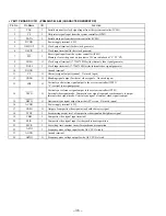
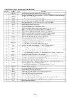
YM-11P BOARD IC903 MB89098RPFV-G-167 (SYSTEM CONTROLLER)
Pin No.
Pin Name
I/O
Function
1
TEST MODE 0
I
Setting terminal for the test mode (Normally: fixed at “L”)
2
TEST MODE 1
I
Setting terminal for the test mode (Normally: fixed at “L”)
3
X0
I
Main system clock input terminal (10 MHz)
4
X1
O
Main system clock output terminal (10 MHz)
5
VSS
—
Ground terminal
6
RESET
I
System reset signal input from the reset signal generator (IC904) “L”" reset
For several hundreds msec. after the power supply rises, “L” is input, then it changes to “H”
7
BB1 ON
O
Bass boost control signal output terminal “H”: bass boost on Not used
8
BB2 ON
O
Bass boost control signal output to the headphone amplifier (IC504) “H”: bass boost on
9
PASSWORD RESET
I
Pass word reset switch (S901) input terminal Password is erased when “L” is input
10
AUDIO MUTE
O
Audio line muting control signal output terminal “H”: muting on
11
VIDEO MUTE
O
Video muting control signal output terminal “H”: muting on
12
SURROUND
O
Surround control signal output terminal “H”: surround on
13
CHECK MODE
O
Screen check mode selection signal output terminal
“L”: screen check mode, “H”: normal mode
14
LANC POWER ON
I
Power supply control input of the LANC “L”: power on Not used (fixed at “H”)
15
BATT IN
I
Power failure detection input terminal
16
PBV
I
Vertical sync reference signal input from the character generator (IC101)
17
DD POWER
O
Power on/off control signal output to the DC/DC converter (IC301) “H”: power on
18
P13/E113
—
Not used (open)
19
BATT IN SW
I
Battery pack detection switch input terminal “L”: battery pack present
20
P15
—
Not used (open)
21
POWER SW
I
Power switch (S701) input terminal (toggle input)
“L” is input when power is turned on/off
22
P17
—
Not used (open)
23
SYSTEM RESET
O
Reset signal output to the character generator (IC101) “L”: reset
24
POWER LED
O
LED drive signal output of the POWER indicator (D701) “H”: LED on
25
CHARGE LED
O
LED drive signal output of the CHARGE indicator (D702) “H”: LED on
26
CMOD
I
Selection input of the clock mode Fixed at “H” in this set
27
AVLS ON
O
AVLS (Automatic Volume Limiter System) control signal output to the headphone amplifier
(IC504) “H”: AVLS on
28
BL ON
O
Back light unit on/off control signal output terminal “H”: back light on
29
SH MUTE
—
Not used (open)
30
P27/RMCI
—
Not used (open)
31
BATT CONT
O
Output of main power control when rechargeable battery is used
“L”: use of DC adapter, “H”: use of rechargeable battery
32
BATT CHK
O
Output of voltage check on/off control in charge mode “H”: voltage check on
33
DC IN MON
I
DC IN detection input terminal “L”: DC present
34
BATT IN MON
I
Dry battery pack detection input terminal “H” is input when battery pack is set
35
DIAL A PHASE
I
Rotary encoder dial pulse input of the screen display/select/enter jog dial (S703)
(A phase input)
36
DIAL B PHASE
I
Rotary encoder dial pulse input of the screen display/select/enter jog dial (S703)
(B phase input)
37
LED015
O
LED drive signal output terminal Not used (open)
38
CS CAM
O
Chip select signal output terminal Not used (open)
Содержание PLM-A55E
Страница 1: ...SERVICE MANUAL GLASSTRON AEP Model UK Model SPECIFICATIONS PLM A55E 9 928 101 31 ...
Страница 3: ... 3 SECTION 1 GENERAL This section is extracted from instruction manual ...
Страница 4: ... 4 ...
Страница 5: ... 5 ...
Страница 6: ... 6 ...
Страница 7: ... 7 ...
Страница 8: ... 8 ...
Страница 9: ... 9 ...
Страница 10: ... 10 ...
Страница 11: ... 11 ...
Страница 12: ... 12 ...
Страница 13: ... 13 ...
Страница 14: ... 14 ...
Страница 48: ... 64 65 66 4 11 SCHEMATIC DIAGRAM SA 52P Board See page 75 for IC Block Diagrams PLM A55E Page 57 ...


