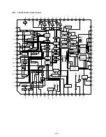
– 38 –
•
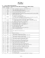
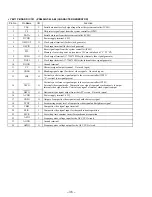
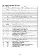
YM-11P BOARD IC201 CXA1950Q-T4 (RGB DECODER)
Pin No.
Pin Name
I/O
Function
1
HUE ADJ
I
HUE adjustment signal input from the D/A converter (IC202)
2
APCTC
I
APC (color synchronization) time constant and VXO free-run frequency adjustment signal input
from the D/A converter (IC202)
3
VXO2
—
System clock connection terminal (4.433619 MHz)
4
VXO1
—
System clock connection terminal (4.433619 MHz)
5
SC OUT
O
Subcarrier output to the A/D, D/A converter (IC103) for Y/C separator
6
GND2
—
Ground terminal (chrominance system)
7
VCC2
—
Power supply terminal (+5V) (chrominance system)
8
B/B-Y
O
RGB B (blue) or RGB matrix color difference signal (B–Y) output terminal
Output of the RGB matrix color difference signal (B–Y) in this set
9
G/Y
O
RGB G (green) or brightness signal output terminal Not used (open)
10
R/R-Y
O
RGB R (red) or RGB matrix color difference signal (R–Y) output terminal
Output of the RGB matrix color difference signal (R–Y) in this set
11
DLAIN
I
Delay line amplifier input from the CCD delay line (IC203)
12
COUT
O
Chroma signal output to the CCD delay line (IC203)
13
ACKTC
—
Connected to the time constant circuit for ACK (auto color killer)
14
DLABIAS
I
Setting terminal for the video mode (NTSC/PAL)
“L”: NTSC mode, “H”: PAL mode (fixed at “H” in this set)
15
SYNC
O
Composite sync signal output terminal “L” active Not used (open)
16
BF
O
Burst flag signal output terminal “L” active Not used (open)
17
YCLPTC
—
Connected to the time constant circuit for pedestal clamp
18
ACKOUT
O
ACK (auto color killer) on/off check signal output terminal
“L”: ACK on (when APC is unlocked), “H”: normal (when APC is locked) Not used (open)
19
ALTOUT
O
Alternate pulse output in PAL mode Not used (open)
20
SYNCTC
—
Connected to the time constant circuit to clamp sync chip for the sync separation
21
VCLPTC
—
Connected to the time constant circuit for pedestal clamp
22
VREG
O
Regulated power supply output terminal (+4.2V)
23
OUTSW
I
For output mode selection Changing over this terminal selects whether RGB signals or color
difference signals are output from the
8
to
!º
pins
“L”: color difference signal output, “H”: RGB output (fixed at “L” in set)
24
VIDEO IN
I
Brightness signal input terminal
25
VCC1
—
Power supply terminal (+5V) (brightness signal system)
26
GND1
—
Ground terminal (brightness signal system)
27
SHPCTL
I
For adjusting the sharpness gain Fixed at center voltage in this set
28
SHPF0
I
For adjusting the frequency for sharpness filter
29
TPADJ
—
For setting the timing of internal pulses
30
CADJ
I
Chroma amplifier gain adjustment signal input from the D/A converter (IC202)
31
ACCTC
—
Connected to the time constant circuit for ACC (auto color control)
32
CIN
I
Chroma signal input terminal
Содержание PLM-A55E
Страница 1: ...SERVICE MANUAL GLASSTRON AEP Model UK Model SPECIFICATIONS PLM A55E 9 928 101 31 ...
Страница 3: ... 3 SECTION 1 GENERAL This section is extracted from instruction manual ...
Страница 4: ... 4 ...
Страница 5: ... 5 ...
Страница 6: ... 6 ...
Страница 7: ... 7 ...
Страница 8: ... 8 ...
Страница 9: ... 9 ...
Страница 10: ... 10 ...
Страница 11: ... 11 ...
Страница 12: ... 12 ...
Страница 13: ... 13 ...
Страница 14: ... 14 ...
Страница 48: ... 64 65 66 4 11 SCHEMATIC DIAGRAM SA 52P Board See page 75 for IC Block Diagrams PLM A55E Page 57 ...

