– 18 –
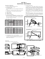
POWER SUPPLY BLOCK
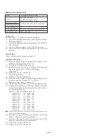
[Power supply voltage check] (YM-11P board)
1. Turn the POWER switch on, and confirm that the POWER LED
(green) lights up.
2. Confirm that the voltage at each check land (CL) on the YM-
11P board satisfies the specification value in Table below. As
the ground, use J101 pin
1
GND.
Input
No signal input
Measuring equipment
Digital voltmeter
V 5.0 V check
Measurement point
CL305
Specification value
4.85 ± 0.10 V
D 5.0 V check
Measurement point
CL307
Specification value
4.95 ± 0.10 V
13.5 V check
Measurement point
CL306
Specification value
13.50 ± 0.20 V
AU 2.0 V check
Measurement point
CL308
Specification value
1.85 ± 0.10 V
BL 7.0 V check
Measurement point
CL310
Specification value
7.00 ± 1.00 V
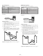
3. Press the battery detection switch (S705) on the SW-312P board.
(Switch with fixed pawl at the lower right of battery)
Or, short CN903 pin
1
and pin
2
on the YM-11P board.
(CHARGE mode becomes active.) At this time, confirm that
the CHARGE LED (orange) lights up.
4. Under this condition, confirm that the voltage of CN301 pin
1
on the YM-11P board is 8.4 ± 0.1 V.
5. After checking, remove a jumper wire used for short in step 3.
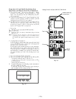
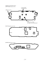
Check Parts:
CN702
S705
[SW-312P board]
(Component side)
CN301
CN903
5
1
1 2
[YM-11P board]
(Component Side)
J101
CL308
CL307
CL310
CL306
L310
Q391
Q392
LND305
L307
CN301
[YM-11P board] (Component Side)
CL305
L601
Q261
Q254
FL252
Содержание PLM-A55E
Страница 1: ...SERVICE MANUAL GLASSTRON AEP Model UK Model SPECIFICATIONS PLM A55E 9 928 101 31 ...
Страница 3: ... 3 SECTION 1 GENERAL This section is extracted from instruction manual ...
Страница 4: ... 4 ...
Страница 5: ... 5 ...
Страница 6: ... 6 ...
Страница 7: ... 7 ...
Страница 8: ... 8 ...
Страница 9: ... 9 ...
Страница 10: ... 10 ...
Страница 11: ... 11 ...
Страница 12: ... 12 ...
Страница 13: ... 13 ...
Страница 14: ... 14 ...
Страница 48: ... 64 65 66 4 11 SCHEMATIC DIAGRAM SA 52P Board See page 75 for IC Block Diagrams PLM A55E Page 57 ...

