– 29 –
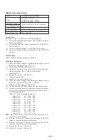
[B Gain Adjustment]
Note:
The view angle correction must be turned off.
Before this adjustment, the Contrast Adjustment must be finished.
Condition:
Input signal
Chroma signal, and color bar signal with burst
signal turned off
Measurement point
RG-46P board CN404 pin
4
and pin
6
Measuring equipment
Oscilloscope
Adjustment page
D
Adjustment address
22
Specification value
± 0.05 V
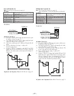
Connection:
Adjustment Procedure:
(1)
Select EXT. VIDEO AUDIO mode, and picture and tone qual-
ity standard setting. (See page 22)
(2)
View angle correction OFF: Connect CN404 pin
2
(EAC OFF)
and pin
1
(GND) on the RG-46P board.
(3)
Connect CH1 of oscilloscope to the CN404 pin
4
, and CH2
to the CN404 pin
6
on the RG-46P board.
(4)
Set (or confirm) data: 01 to page: 1, address: 00.
(Cancel D page protect)
(5)
On page: D, address: 22, change data with the PLAY and STOP
buttons and press the PAUSE button to write data so that a
difference between
D
' level of waveform on the CH2 of os-
cilloscope and
D
evel (
D
level of Contrast Adjust-ment) on
the CH1 satisfies the specification value.
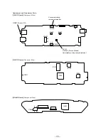
Adjustment and Adjustment Parts: RG-46P board (see page 33)
D
'
2H
[R Brightness Adjustment]
Note:
The view angle correction must be turned off.
Before this adjustment, the Contrast Adjustment must be finished.
Condition:
Input signal
Chroma signal, and color bar signal with burst
signal turned off
Measurement point
RG-46P board CN404 pin
4
and pin
8
Measuring equipment
Oscilloscope
Adjustment page
D
Adjustment address
27
Specification value
± 0.05 V
Connection:
Adjustment Procedure:
(1)
Select EXT. VIDEO AUDIO mode, and picture and tone qual-
ity standard setting. (See page 22)
(2)
View angle correction OFF: Connect CN404 pin
2
(EAC OFF)
and pin
1
(GND) on the RG-46P board.
(3)
Connect CH1 of oscilloscope to the CN404 pin
4
, and CH2
to the CN404 pin
8
on the RG-46P board.
(4)
Set (or confirm) data: 01 to page: 1, address: 00.
(Cancel D page protect)
(5)
On page: D, address: 27, change data with the PLAY and STOP
buttons and press the PAUSE button to write data so that a
difference between
E
' level of waveform on the CH2 of os-
cilloscope and
E
level (
E
level of RGB Brightness Adjust-
ment) on the CH1 satisfies the specification value.
Adjustment and Adjustment Parts: RG-46P board (see page 33)
Ch1
Ch2
CN404 pin
8
(R OUT)
CN404 pin
1
(GND)
RG-46P Board
Oscilloscope
(DC range)
CN404 pin
4
(G OUT)
CN404 pin
1
(GND)
2H
E
'
Ch1
Ch2
CN404 pin
6
(B OUT)
CN404 pin
1
(GND)
RG-46P Board
Oscilloscope
(DC range)
CN404 pin
4
(G OUT)
CN404 pin
1
(GND)
Содержание PLM-A55E
Страница 1: ...SERVICE MANUAL GLASSTRON AEP Model UK Model SPECIFICATIONS PLM A55E 9 928 101 31 ...
Страница 3: ... 3 SECTION 1 GENERAL This section is extracted from instruction manual ...
Страница 4: ... 4 ...
Страница 5: ... 5 ...
Страница 6: ... 6 ...
Страница 7: ... 7 ...
Страница 8: ... 8 ...
Страница 9: ... 9 ...
Страница 10: ... 10 ...
Страница 11: ... 11 ...
Страница 12: ... 12 ...
Страница 13: ... 13 ...
Страница 14: ... 14 ...
Страница 48: ... 64 65 66 4 11 SCHEMATIC DIAGRAM SA 52P Board See page 75 for IC Block Diagrams PLM A55E Page 57 ...


