


78
Configuring Sensor Inputs
C
h
a
p
te
r 4
A
ppli
c
at
ion S
e
ttings
3
Click [Apply].
The logical sensor input pin is added.
Deleting Logical Sensor Input Pins
Created for NSR
The physical sensor input pins of NSR that exist by default
cannot be deleted.
1
Open [I/O Device] in the [Device] tree, and click to
select [System I/O].
2
Select the check boxes for the logical sensor input pins
you want to delete in the [Logical Sensor In] tab, and
click [Delete].
The logical sensor input pin is deleted.
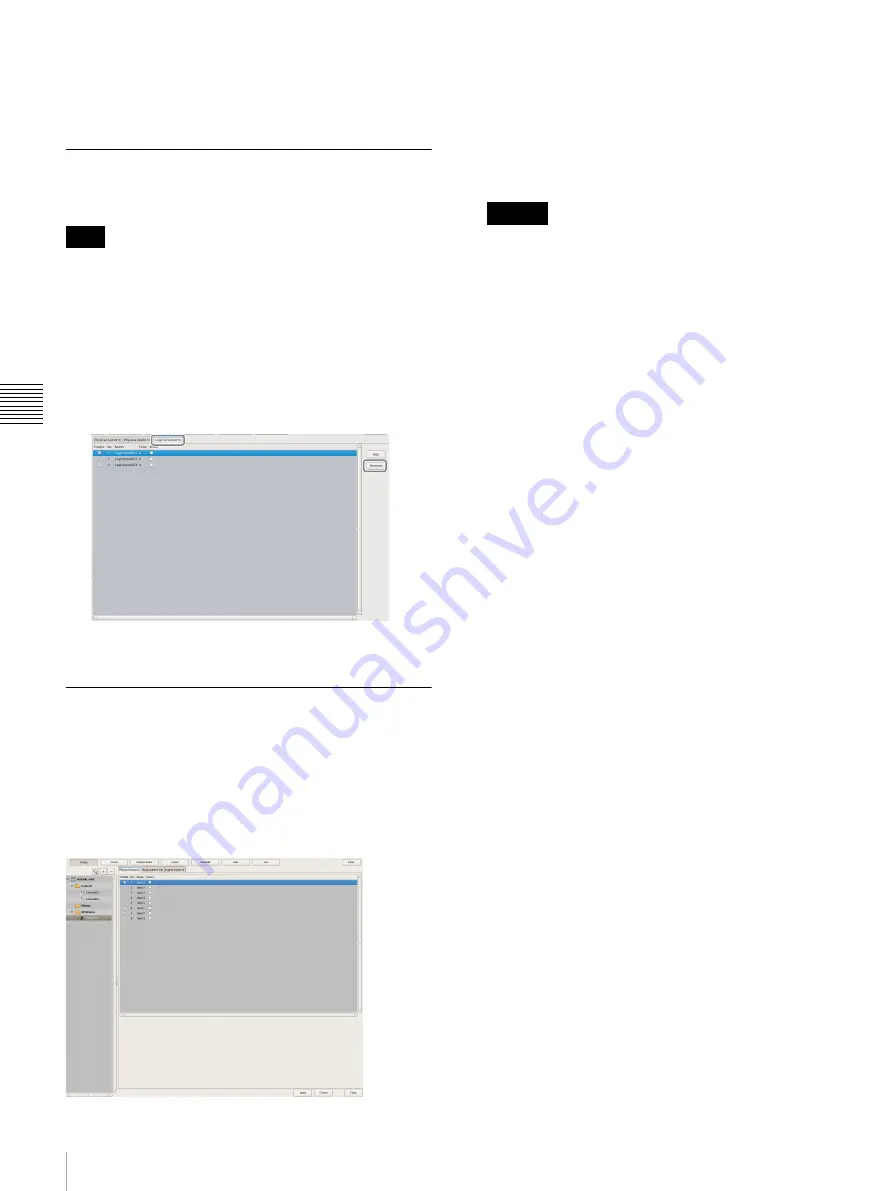
Setting Items of the [Logical Sensor
In] Tab
You can configure sensor input pins.
After configuring each item, click [Apply] to save your
settings.
This example describes the screen for configuring logical
sensor input pins of the NSR.
Sensor Input Pin List
This displays a list of the sensor input pins configured for
the device selected in the tree structure.
Enable
Select the check boxes to enable the pins for the sensor
inputs.
To use sensor inputs, the sensor input pin settings on
the device must also be enabled.
No
This displays the numbers of the sensor input pins.
This item cannot be changed.
Name
Enter the names of the sensor inputs.
Pulse
Enter the duration to sustain pulse input once it is
turned on within the range of 0 to 60,000 milliseconds.
If pulses of short duration persist and there is a high
frequency of on/off switching as a result of this
configuration, multiple inputs may be grouped
together as one pulse.
Invert
Select the check box to invert the pulse polarity.
Example: Invert ON
→
OFF to OFF
→
ON.
Add
This adds a logical sensor input pin to the list.
This item is only displayed for the logical sensor inputs of
“System I/O.”
Delete
This deletes the selected sensor input pin from the list.
This item is only displayed for the logical sensor inputs of
“System I/O.”
Note
Caution
Содержание NSR-500
Страница 117: ...117 System Administration Chapter 5 Operation and Control 4 Click Close The Export screen closes ...
Страница 133: ......


