– 25 –
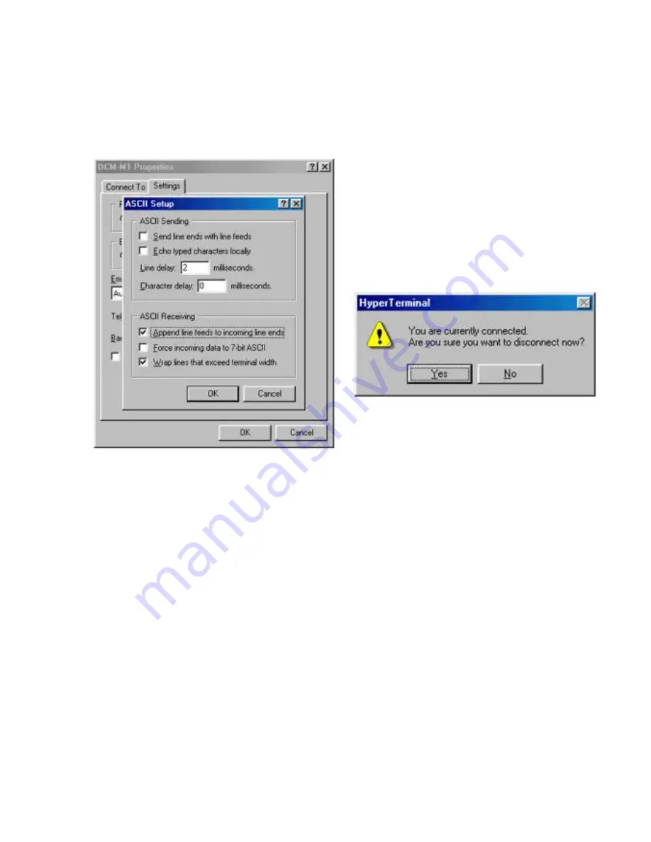
5) On the [ASCII Setup] screen, set the following and click [OK].
[ASCII Sending]
Line delay: [2] milliseconds
[ASCII Receiving]
[Append line feeds to incoming line ends]: [
√
] marking
[Wrap lines that exceed terminal width]: [
√
] marking
Next, on the [Settings] screen, click [OK] once more.
Fig.7-2-6
4. Setting of the Set
After the Hyper Terminal setting finished, check that the prompt
appears on the screen, and then perform a setting to the set through
the steps given below.
1) Set the POWER switch to PLAY/EDIT.
Note:
Setting the POWER switch to CAMERA/INTERVIEW al-
lows the Auto Power OFF function to operate, thus caus-
ing the power to be turned off during measurement. There-
fore, be sure to set it to PLAY/EDIT.
2) Short the test pins TP8047 (TEST) and TP5002 (GND) with
tweezers, etc.
3) From the AC Adaptor, turn the power on.
4) Remove tweezers to release the test pins.
5) Check that the following message is displayed on the screen.
Board Check Monitor ver1.XXX
5. Exit Hyper Terminal
From the File on the menu bar, click the “Exit Hyper Terminal”.
On the following screen, click [Yes] to finish the Hyper Terminal.
Fig.7-2-7
Содержание MDDISCAM DCM-M1
Страница 5: ...1 1 SECTION 1 GENERAL This section is extracted from in struction manual 3 866 152 11 DCM M1 ...
Страница 6: ...1 2 ...
Страница 7: ...1 3 ...
Страница 8: ...1 4 ...
Страница 9: ...1 5 ...
Страница 10: ...1 6 ...
Страница 11: ...1 7 ...
Страница 12: ...1 8 ...
Страница 13: ...1 9 ...
Страница 14: ...1 10 ...
Страница 15: ...1 11 ...
Страница 16: ...1 12 ...
Страница 17: ...1 13 ...
Страница 18: ...1 14 ...
Страница 19: ...1 15 ...
Страница 20: ...1 16 ...
Страница 21: ...1 17 ...
Страница 22: ...1 18 ...
Страница 23: ...1 19 ...
Страница 24: ...1 20 ...
Страница 25: ...1 21 ...
Страница 26: ...1 22 ...
Страница 27: ...1 23 ...
Страница 28: ...1 24 ...
Страница 29: ...1 25 ...
Страница 30: ...1 26 ...
Страница 31: ...1 27 ...
Страница 32: ...1 28 ...
Страница 33: ...1 29 ...
Страница 34: ...1 30 1 30 E ...
Страница 47: ...2 13 MEMO ...
Страница 69: ...DCM M1 4 5 4 6 4 7 4 8 4 1 FRAME SCHEMATIC DIAGRAM FRAME ...
Страница 96: ...DCM M1 4 115 4 113 4 114 ETHER INTERFACE ETHER ...
Страница 98: ...DCM M1 4 119 4 120 AV IN OUT JACK JACK AV IN OUT SCHEMATIC DIAGRAM See page 4 121 for printed wiring board ...
Страница 99: ...DCM M1 4 121 JACK AV IN OUT PRINTED WIRING BOARD Ref No JACK board 20 000 series 4 122 AV IN OUT JACK ...
Страница 173: ...DCM M1 33 34 35 LCD LCD Signal Paths were Missing in Service Manual LCD LCD SCHEMATIC DIAGRAM Page 4 106 to 4 108 ...
Страница 196: ... 22 FOR CAMERA OPTICAL AXIS ADJUSTMENT 0 180 90 67 5 22 5 337 5 292 5 247 5 202 5 157 5 112 5 8 4 5 7 1 6 2 3 270 ...


