– 16 –
4) Operating the keys on the set, enter the Test mode.
5) Select the item “7-02-01” and press
u
key to activate the
Switch Check mode.
Note:
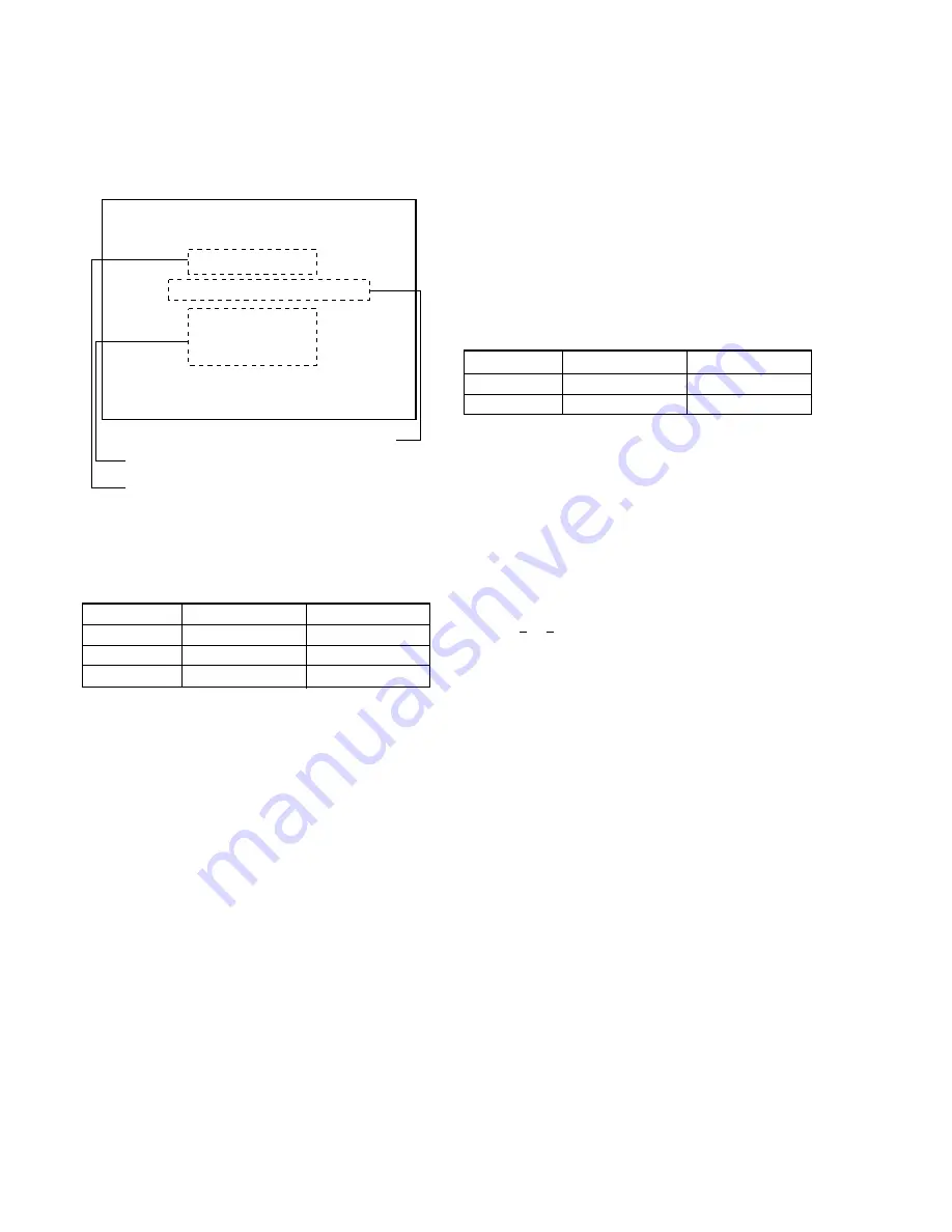
When the Switch Check mode becomes active, the
screen as shown in Fig.7-1-23 appears.
Fig.7-1-23
6) Press each switch at part
C
to check that the mecha. deck
switch status display on the LCD screen changes as listed be-
low. (Disc type check switch)
Switch name
When not pressed
When pressed
MD1/MD2
MD2
MD1
PIT/GRV
GRV
PIT
PROTECT SW
ON
OFF
Table 7-1-5
7) Check that the Optical Pick-up block moves outward when
>
key is pressed, or it moves inward when
.
key is
pressed. (Sled motor check)
8) At this time, check that the part
B
also moves in the same
direction as the direction in which the Optical Pick-up block
moves. (Tracking coil check)
9) Check that when the Optical Pick-up block moves inward as
far as it will go, the IN LIMIT SW status display on the LCD
screen is “ON” and when it moves outward, the switch be-
comes “OFF”. (IN LIMIT SW check)
10) Check that the part
D
moves in arrow direction when
y
key
is pressed, and it returns to original position when
y
key is
pressed once more. (HEAD UP/DOWN motor check)
11) At this time, check that each time the
y
key is pressed, the
INITIAL SW status display on the LCD screen changes over
between “ON” and “OFF”. (INITIAL SW check)
12) Turn the power off.
Note:
Disconnect the AC adapter to turn the power off, be-
cause the POWER switch is inactive in the Test mode.
SW CHECK MODE
REVERSE/CLOSE
COVER
CLOSE
OFF
EJECT SW
IN LIMIT SW
INITIAL SW
MD1/MD2
PIT/GRV
PROTECT SW
OFF
OFF
MD2
GRV
ON
LCD
Mecha. deck switch status display
Set switch status display
LCD switch status display
1-5.
MAC Address Setting
The MAC address must be unique in the world.
On this set, hexadecimal MAC address is set for every serial num-
ber of the set.
1. How to Get MAC Address
1) Read the lower 5 digits of serial No. and add “291903 (deci-
mal)” to it, which is assumed to be D
1
.
D
1
= “Lower 5 digits of serial No.” + 291903
Example: If the lower 5 digits of serial No. is “03574”
D
1
= 3574 + 291903 = 295477
2) From Table 7-1-6, obtain D
2
and H
1
that correspond to D
1
Example: If D
1
= 295477
D
2
= 295477 – 262144 = 33333
H
1
= 04
D
1
(decimal)
D
2
(decimal)
H
1
(hexadecimal)
327679 or less
D
1
-262144
04
327680 or more
D
1
-327680
05
Table 7-1-6
3) From Table 7-1-7, obtain maximum decimal number not ex-
ceeding D
2
, which is assumed to be D
3
.
Example: If D
2
= 33333
D
3
= 33280
4) From Table 7-1-7, obtain hexadecimal number that corresponds
to D
3
, and the higher 2 digits of that number is assumed to be
H
3
.
Example: If D
3
= 33280
H
3
= 82
5) Obtain a difference between D
2
and D
3
, which assumed to be
D
4
. (0
≤
D
4
≤
255)
D
4
= D
2
– D
3
Example: If D
2
= 33333 and D
3
= 33280,
D
4
= 33333 – 33280 = 53
6) From Table 7-1-8, convert D
4
into hexadecimal number to ob-
tain H
4
.
Example: If D
4
= 53
H
4
= 35
7) The MAC address is “08:00:46:H
1
:H
3
:H
4
”. (08, 00, 46 are fixed
values)
Example: If H
1
= 04, H
3
= 82 and H
4
= 35
08:00:46:04:82:35
Содержание MDDISCAM DCM-M1
Страница 5: ...1 1 SECTION 1 GENERAL This section is extracted from in struction manual 3 866 152 11 DCM M1 ...
Страница 6: ...1 2 ...
Страница 7: ...1 3 ...
Страница 8: ...1 4 ...
Страница 9: ...1 5 ...
Страница 10: ...1 6 ...
Страница 11: ...1 7 ...
Страница 12: ...1 8 ...
Страница 13: ...1 9 ...
Страница 14: ...1 10 ...
Страница 15: ...1 11 ...
Страница 16: ...1 12 ...
Страница 17: ...1 13 ...
Страница 18: ...1 14 ...
Страница 19: ...1 15 ...
Страница 20: ...1 16 ...
Страница 21: ...1 17 ...
Страница 22: ...1 18 ...
Страница 23: ...1 19 ...
Страница 24: ...1 20 ...
Страница 25: ...1 21 ...
Страница 26: ...1 22 ...
Страница 27: ...1 23 ...
Страница 28: ...1 24 ...
Страница 29: ...1 25 ...
Страница 30: ...1 26 ...
Страница 31: ...1 27 ...
Страница 32: ...1 28 ...
Страница 33: ...1 29 ...
Страница 34: ...1 30 1 30 E ...
Страница 47: ...2 13 MEMO ...
Страница 69: ...DCM M1 4 5 4 6 4 7 4 8 4 1 FRAME SCHEMATIC DIAGRAM FRAME ...
Страница 96: ...DCM M1 4 115 4 113 4 114 ETHER INTERFACE ETHER ...
Страница 98: ...DCM M1 4 119 4 120 AV IN OUT JACK JACK AV IN OUT SCHEMATIC DIAGRAM See page 4 121 for printed wiring board ...
Страница 99: ...DCM M1 4 121 JACK AV IN OUT PRINTED WIRING BOARD Ref No JACK board 20 000 series 4 122 AV IN OUT JACK ...
Страница 173: ...DCM M1 33 34 35 LCD LCD Signal Paths were Missing in Service Manual LCD LCD SCHEMATIC DIAGRAM Page 4 106 to 4 108 ...
Страница 196: ... 22 FOR CAMERA OPTICAL AXIS ADJUSTMENT 0 180 90 67 5 22 5 337 5 292 5 247 5 202 5 157 5 112 5 8 4 5 7 1 6 2 3 270 ...


