– 20 –
1-6.
Touch Panel Adjustment
1. Touch Panel Position Alignment
The touch panel position alignment should be made in both cases
where the LCD screen is opened, and it is closed.
In touching the screen, use the input pen attached.
Adjusting method
1) Select the item number “7-01-02”.
2) Press
u
key to activate the Touch Panel Position Alignment
mode.
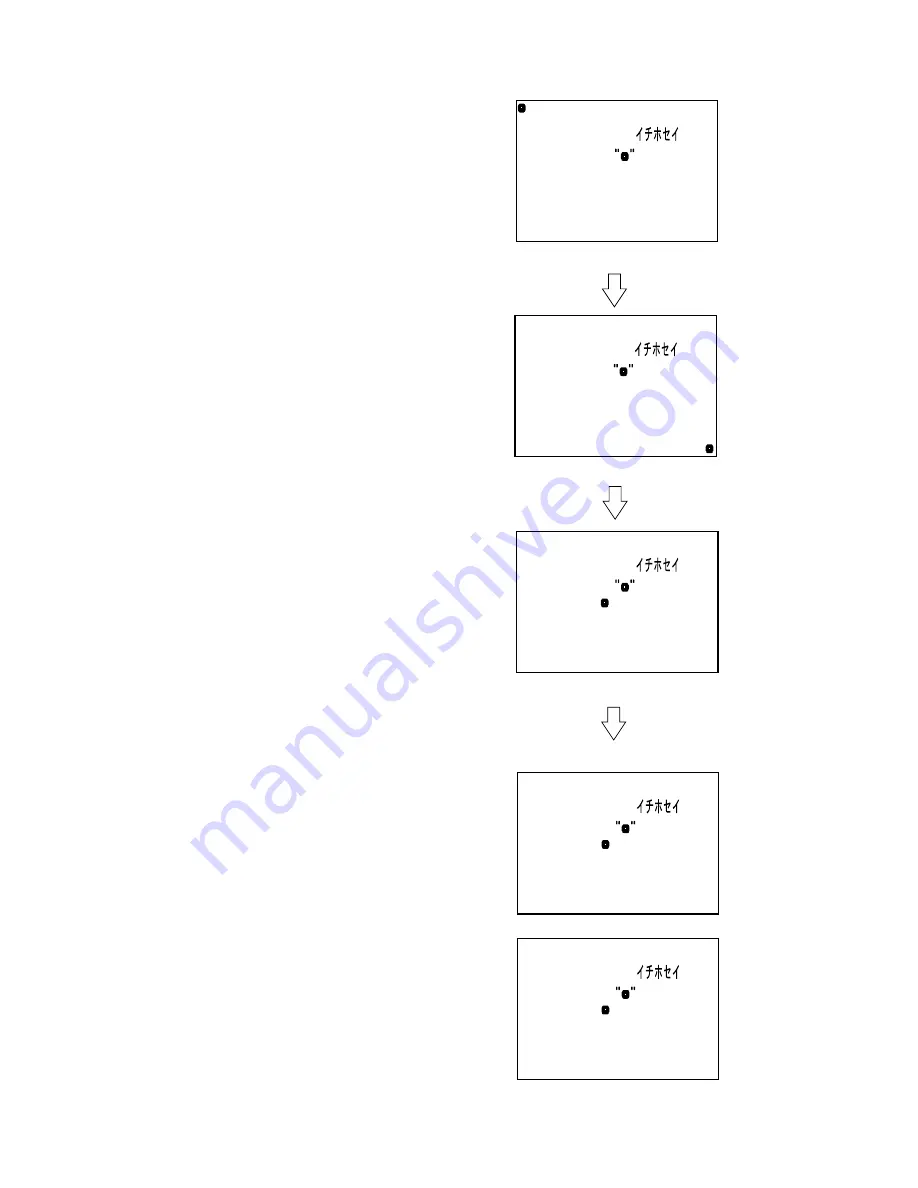
(The screen display will be as shown in Fig.7-1-25)
3) Touch the center of mark displayed at the upper left of LCD
screen.
(The screen display switches to the one shown in Fig.7-1-26)
4) Touch the center of mark displayed at the lower right of LCD
screen.
(The screen display switches to the one shown in Fig.7-1-27)
5) Touch the center of mark displayed in the center of LCD screen.
6) The touch panel position alignment finishes, and the adjust-
ment result is displayed.
• If alignment is successful ........... “OK!”
• If alignment failed ...................... “NG!”
7) If the touch panel alignment is to be made once more by chang-
ing the direction of the LCD, press
u
key to display the screen
shown in Fig.7-1-25, and then perform adjustment after step
3).
Note:
If the alignment failed, perform the touch panel posi-
tion alignment again without changing the LCD direc-
tion.
8) At successful completion of the alignment in both cases where
the LCD is opened and closed, press
x
key to release the Touch
Panel Position Alignment mode.
2. Touch Panel Simple Check
Checking method
1) Select the item number “7-01-03”.
2) Check that “OK” is displayed when you touch the LCD screen.
Fig.7-1-25
Fig.7-1-26
Fig.7-1-27
Fig.7-1-28
Touch Panel
Please Touch
Touch Panel
Please Touch
Touch Panel
Please Touch
Touch Panel
NG!
Please Touch
Touch Panel
OK!
Please Touch
• In case of NG adjustment
• In case of successful adjustment
Содержание MDDISCAM DCM-M1
Страница 5: ...1 1 SECTION 1 GENERAL This section is extracted from in struction manual 3 866 152 11 DCM M1 ...
Страница 6: ...1 2 ...
Страница 7: ...1 3 ...
Страница 8: ...1 4 ...
Страница 9: ...1 5 ...
Страница 10: ...1 6 ...
Страница 11: ...1 7 ...
Страница 12: ...1 8 ...
Страница 13: ...1 9 ...
Страница 14: ...1 10 ...
Страница 15: ...1 11 ...
Страница 16: ...1 12 ...
Страница 17: ...1 13 ...
Страница 18: ...1 14 ...
Страница 19: ...1 15 ...
Страница 20: ...1 16 ...
Страница 21: ...1 17 ...
Страница 22: ...1 18 ...
Страница 23: ...1 19 ...
Страница 24: ...1 20 ...
Страница 25: ...1 21 ...
Страница 26: ...1 22 ...
Страница 27: ...1 23 ...
Страница 28: ...1 24 ...
Страница 29: ...1 25 ...
Страница 30: ...1 26 ...
Страница 31: ...1 27 ...
Страница 32: ...1 28 ...
Страница 33: ...1 29 ...
Страница 34: ...1 30 1 30 E ...
Страница 47: ...2 13 MEMO ...
Страница 69: ...DCM M1 4 5 4 6 4 7 4 8 4 1 FRAME SCHEMATIC DIAGRAM FRAME ...
Страница 96: ...DCM M1 4 115 4 113 4 114 ETHER INTERFACE ETHER ...
Страница 98: ...DCM M1 4 119 4 120 AV IN OUT JACK JACK AV IN OUT SCHEMATIC DIAGRAM See page 4 121 for printed wiring board ...
Страница 99: ...DCM M1 4 121 JACK AV IN OUT PRINTED WIRING BOARD Ref No JACK board 20 000 series 4 122 AV IN OUT JACK ...
Страница 173: ...DCM M1 33 34 35 LCD LCD Signal Paths were Missing in Service Manual LCD LCD SCHEMATIC DIAGRAM Page 4 106 to 4 108 ...
Страница 196: ... 22 FOR CAMERA OPTICAL AXIS ADJUSTMENT 0 180 90 67 5 22 5 337 5 292 5 247 5 202 5 157 5 112 5 8 4 5 7 1 6 2 3 270 ...


