9 (E)
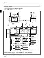
System Connection Example
Major system components
This system are composed with S-BUS data link
connected with 75-ohm coaxial cables as its core.
The major components of the S-BUS data link are
listed below.
Note
Although you may use a switcher other than the HDS-
X3000 series for the primary station, some functions
are limited.
Notes on connections
• Set the P/S switch on the internal CPU board of the
routing switcher to be used for the primary station to
P (or to M when the switch designation is M/S).
• Set the M/S switch on the internal CPU board of the
routing switcher (or the P/S switch if the switcher is
HDS-X3000-series switcher) to be used for a
secondary station to S.
• A maximum of 128 routing switchers and control
units can be connected to one S-BUS line.
• The coaxial cable can be extended up to 500 meters
when a BELDEN 8281 or equivalent cable is used.
• Be sure to terminate the T-bridge attached to the last
unit of the S-BUS line and the unused REMOTE 1
connectors of each switcher with 75-ohm terminators.
• Only one of the REMOTE 1 connectors can be used
on the routing switcher used for a secondary station.
• The optional BKS-R1607/R1608/R3209/R3210
control units (version 3.00 or higher) can be connected
to the REMOTE 4 connector (monitor line).
How to use the T-bridge (type B)
A T-bridge of type B is supplied with the HDS-X3000-
series switcher. To use them, connect as follows to
coaxial cables shorter than 50 cm (19
3
/
4
inches):
T-bridge
(type B)
BELDEN 8281 cable (less than
50 cm or 19
3
/
4
inches) or
equivalent
REMOTE 1 connector
(BNC, female)
Configuration of an S-BUS data link
Description
on the S-BUS
data link
Equipment
Quantity
Function
Primary station
Multi bit rate routing switcher
HDS-X3700
1
Communication control over the entire
S-BUS data link. Simultaneously operable
as a secondary station.
Secondary
Video routing switcher
DVS-V6464B/M 253 max.
Communication control in each unit.
stations
Multi bit rate routing switcher HDS-X3600
Each performs communication according to
HDS-X3400
instructions from the primary station.
Audio routing switcher
DVS-A3232
RS-422A routing switcher
DVS-RS1616
Time code routing switcher
DVS-TC3232
X-Y control unit
BKS-R3210
32-button control unit
BKS-R3209
Universal control unit
BKS-R1607
16-button control unit
BKS-R1608
Source/destination control unit BKS-R3205
8-destination control unit
BKS-R3206
Single status display unit
BKS-R3280
Single status display unit
BKS-R3281
Terminal
Terminal emulator
General PC
1
Various system settings.
Indication and control of errors that are
generated in the S-BUS line.
Switcher
Remote control unit


