4-54
Chapter 4 Adjustments and Settings for Recording
4
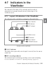
!£
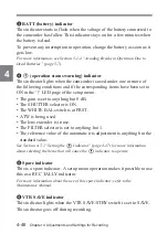
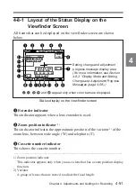
Gain indicator
This indicator indicates the gain (in dB) of the video amplifier, as set by
the GAIN selector.
!¢
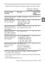
White balance memory indicator
This indicator indicates the currently selected white balance automatic
adjustment memory.
A: The WHITE BAL switch is set to A.
B: The WHITE BAL switch is set to B.
P: The WHITE BAL switch is set to PRST.
M: The WHITE BAL switch of the RM-P9 Remote Control Unit is set
to MANUAL.
T: ATW is being used.
!∞
Filter indicator
This indicator indicates the currently selected filter types.
!§
16:9 mode indicator (DNW-90WS/90WSP/9WS/9WSP only)
This indicates the 16:9 mode.
!¶
Time code indicator
This indicates the time code, user bits or other information selected by
the DISPLAY switch and DATA DISPLAY switch settings.
For more information, see the section “Relationships between the DISPLAY switch
and DATA DISPLAY switch settings and the time counter displays” (page 2-40).
!•
ID number indicator
This indicates the ID number selected from ID1 to ID4. This indicator is
recorded together with the color bars.
!ª
Date and time indicator
This shows the date and time of recording. This indicator is recorded
together with the color bars.
Содержание DNW-7
Страница 12: ......
Страница 24: ......
Страница 41: ...Chapter 2 Locations and Functions of Parts and Controls 2 17 2 Shooting and record playback functions 2 ª ...
Страница 192: ......
Страница 234: ...5 42 Chapter 5 Setting Up the Camcorder 5 Insert the viewfinder barrel here Velcro tape Velcro tape Drawstring ...
Страница 238: ......
Страница 280: ......
Страница 281: ......
Страница 282: ...Name Office Address Phone ...

