125
Using Keys to Compose Video
Cha
pte
r 4
B
as
ic
O
per
at
io
ns
2
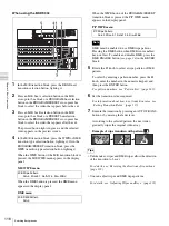
In the KEYER block, press the CK button.
A CK Manual sub menu appears in the display panel.
3
Adjust the parameters.
Chroma key (CK) parameters (Chroma Key menu)
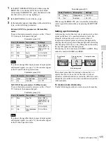
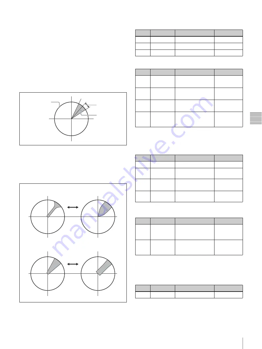
When viewed on a vectorscope, the part of the foreground
that becomes the key signal (the part that is replaced by the
background) appears as a fan shaped area centered around
the keying color (see the following figure).
You can adjust the shape of this area by adjusting the
Angle parameter. You can also adjust the Y, C, and key
signals individually.
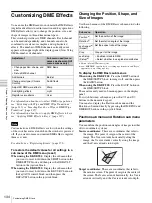
When there are patches of the background color in the
foreground picture, you can remove those patches from the
foreground picture (color cancel function). You can
suppress the Y component of the video, and also use two
parameters (C1 and C2) to adjust the chroma components
(see figures below)
.
a) Enabled only when Color cancel is set to On.
b) Affects only Y signal of foreground video.
c) Affects only C signals of foreground video.
d) Affects only key signals.
a) The C1 setting is ignored when C2 is anything other than 0.00.
To adjust key opacity
Use the Other sub menu to adjust the opacity of chroma
keys.
The Other sub menu has the following parameter.
SAT: 100%
Hue of keying color
Angle
Area removed
by chroma key
Adjust with C2
Adjust with C1
C1: Small C1: Large
C2: Small C2: Large
Parameter group (1/4)
Knob
Parameter
Description
Settings
F2
Hue
Keying color hue
0.0 to 359.5
F3 GN
Gain
0.0
to
63.99
F4
Clp
Key reference level
0.0 to 100.0
Parameter group (2/4)
Knob
Parameter
Description
Settings
F1
Y
Offset value vs.
Angle
a) b)
–45.00 to
45.00
F2
C
Offset value vs.
Angle
a) c)
–45.00 to
45.00
F3
K
Offset value vs.
Angle
d)
–45.00 to
45.00
F4
Ang
Angle of the area
that becomes the
key signal (Angle)
5.00 to 90.00
Parameter group (3/4)
Knob
Parameter
Description
Settings
F1 Col
Color
cancel
On/Off
F2 Y
Suppression
of
Y
component
0.00 to 31.99
F3
C1
Suppression by C1
parameter
a)
0.00 to 31.99
F4
C2
Suppression by C2
parameter
0.0 to 100.0
Parameter group (4/4)
Knob
Parameter
Description
Settings
F1 ShL
Positional
adjustment of left
side of key signal
0 to 3
F2 ShR
Positional
adjustment of right
side of key signal
0 to 3
Knob
Parameter
Description
Settings
F1
Opac
Opacity
0.0 to 100.0
Содержание DFS-900M
Страница 189: ...189 Pattern List Appendix Pattern List Wipe Basic wipe ...
Страница 190: ...190 Pattern List Appendix User wipe ...
Страница 191: ...191 Pattern List Appendix Mask ...
Страница 193: ...193 Pattern List Appendix ...
Страница 194: ...194 Pattern List Appendix 3D DME effects ...
Страница 195: ...195 Pattern List Appendix ...
Страница 196: ...196 Pattern List Appendix User effects ...
Страница 215: ...215 External Dimensions Appendix External Dimensions BKDF 901 1M E Control Panel Unit mm inches ...
Страница 216: ...216 External Dimensions Appendix BKDF 902 1 5M E Control Panel Unit mm inches ...
Страница 217: ...217 External Dimensions Appendix DFS 900M Processor Unit Unit mm inches ...


