21
Instruction for use | Supercal 5
4.7.3 Installation Guidelines for Temperature Sensors According to EN1434
4.7.3.1 Compliance With the Operating Conditions According to MID
for the Temperature Sensors
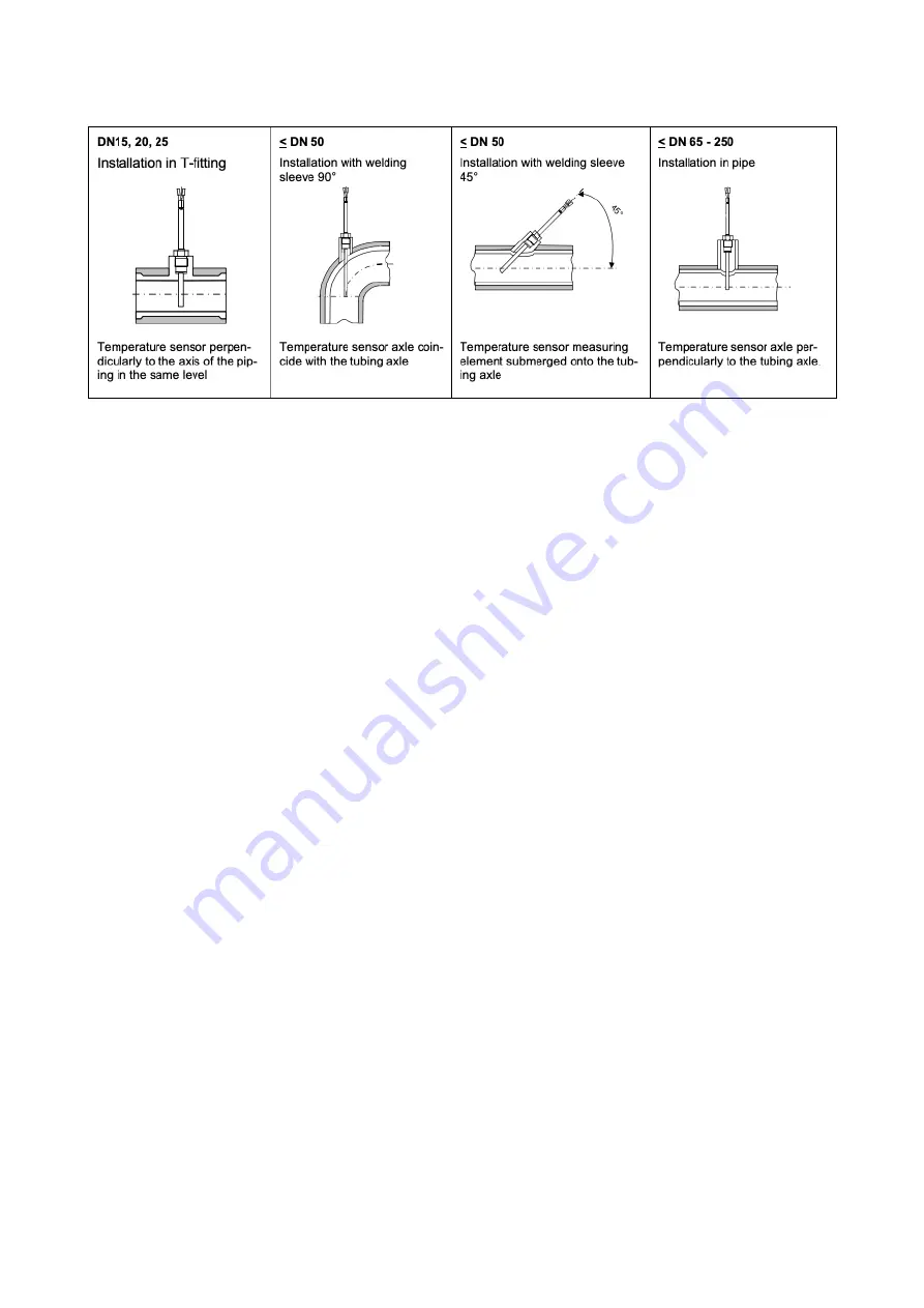
The temperature sensors must be installed symmetrically in the flow and return pipes pref
-
erably directly. If temperature sensors are installed with pockets, both must be tested for
conformity. The tips of the temperature sensors should sit cleanly on the thermowell bot-
toms. Installation points in the flow sensor can be used if the temperature sensors are in
-
stalled symmetrically.
If the temperature sensors are permanently connected, the connecting cables must not be
shortened.
Interchangeable temperature sensors with conformity markings allow a maximum length of
15 m with equal length for flow and return.
EN 1434-2 applies to the cable cross-sections. Care must be also be taken to ensure that the
calculator is electrically compatible with the temperature sensors:
The calculator has been designed for Pt500 temperature sensors. Don't use other
sensors.
To prevent unauthorized access, the installation points must be sealed last.
4.8 Installation Check
For the installation of the heat meter and the associated temperature sensors, the general
installation regulations according to EN 1434 Part 6 and the PTB Technical Guideline TR-K 9
must be adhered to. Guideline TR-K 9 is available for download on the PTB website.
After the shut-off valves have been opened, the installation must be checked for leaks. By
repeatedly pressing the orange operating button, various operating parameters can be read
on the LCD display of the calculator, e. g. flow rate, power, and flow and return temperature.
The communication indicator on the LCD display can be used to check the communication
input or output. The Superprog software can also be used to simulate communication out-
puts. The flow rate can be checked using the flow rate indicator. The dynamics of the flow
sensor can be checked using the current flow display in conjunction with flow control.
All parameter displays are used to check the meter or to adjust the system. Check that the
adjusted flow rate of the system does not exceed the maximum permitted flow rate of the
meter. It is recommended that an installation protocol is made using the Android NFC tool or
the optical interface with the Superprog software for complete functional testing.
Содержание Supercal 5 I
Страница 1: ...Instructions for Use Supercal 5 I...
Страница 6: ...6 Instruction for use Supercal 5...
Страница 55: ...55 Instruction for use Supercal 5 The interfaces of the NOWA adapter...
Страница 66: ......
Страница 67: ......
Страница 68: ...Sontex SA Rue de la Gare 27 CH 2605 Sonceboz Tel 41 32 488 30 00 sontex sontex ch www sontex ch 21 10...


