Date de création : 19/11/07
Indice de révision : C
15
1. Indication de sécurité
1. Notes on safety
1. Sicherheitshinweise
2. Mise en service
2. Start up
2. Inbetriebnahme
3. Utilisation
3. Handling
3. Handhabung
4. Maintenance
4. Maintenance
4. Instandhaltung
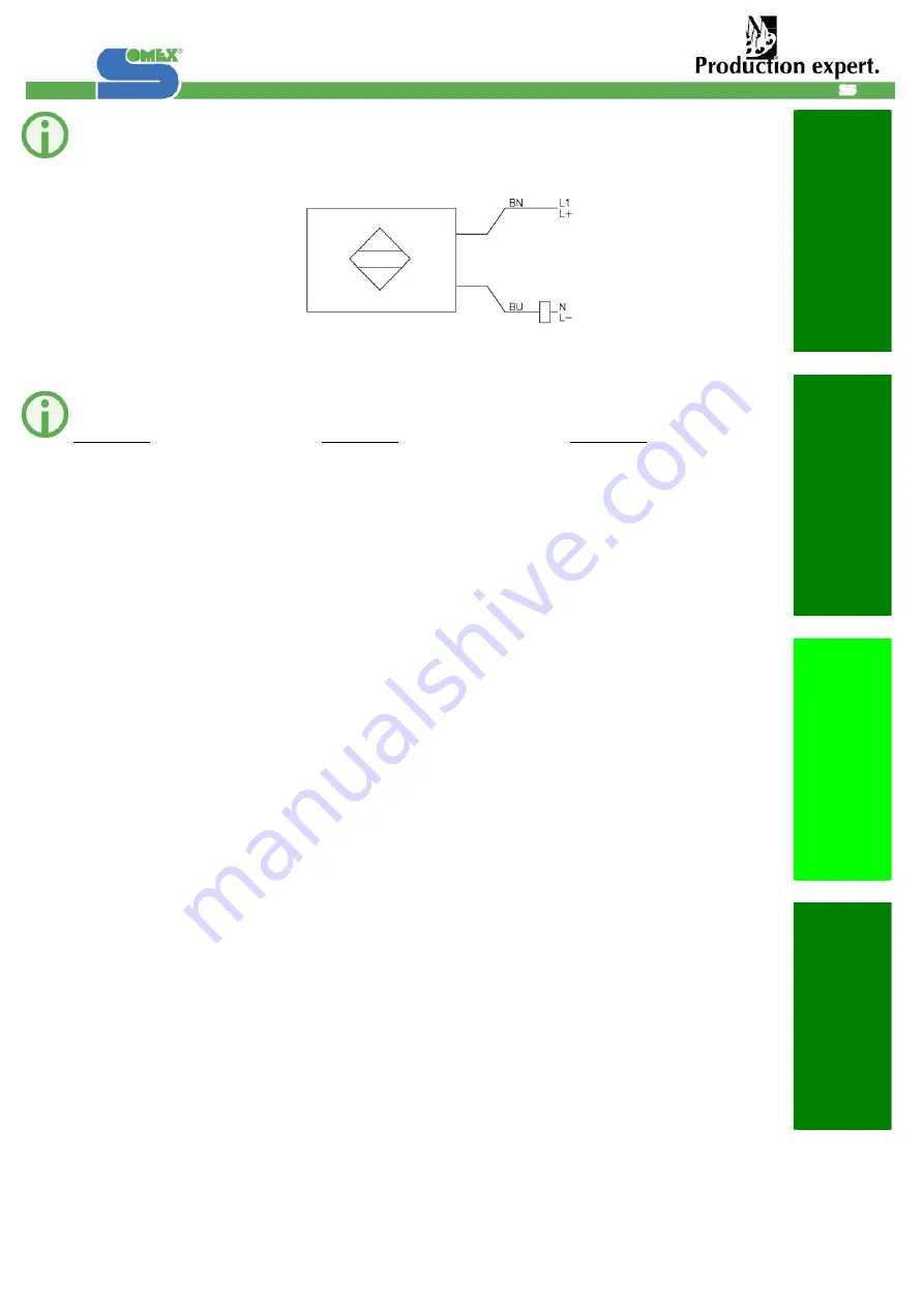
Branchements électrique du
capteur du vérin pneumatique :
Electrical connections from the
pneumatic cylinder:
Elektrischen Anschlüsse des
Sensors des
Pneumatikzylinders:
BU : Couleur Bleu
BN : Couleur Brun
BU : Blue colour
BN : Brown colour
BU: Farbe Blau
BN: Farbe Braun
3.2 Réglages
MAX30-BS
Réglage complet du pot de
serrage (lors d'un changement
des rondelles élastiques par
exemple).
3.2 Adjustments
MAX30-BS
Complete setting of the
clamping System (after
replacement of spring rings for
example).
3.2 Stellung
MAX30-BS
Komplette Einstellung des
Werkzeugspanners ( Zum
Beispiel nach Austausch der
Tellerfedern)
Réglage du serrage
Relever les cotes B et S.
Calculer la cote R de la
manière suivante:
R = 176,12 + S – B
Monter le tirant, la pince, les
rondelles et le porte-outil.
Mettre en place la cote R.
Relever la cote T.
Réglage de l'éjection
Cone monté en broche.
Relever les cote C et D
Vérifier que :
C - D = J = 3mm
Si nécessaire retoucher la
pièce (1) pour obtenir les 3 mm.
Assurer le serrage
Désserrer l' écrou (2) et sortir le
cone de la broche
Remettre en place la cote T
Relever la cote R
R doit etre supérieur d'environ
1mm par rapport au R relever
dans le paragraphe ci dessus.
Setting of the clamping force
Recording of the dimensions B
and S
Calculation of the dimension
according to the following
Formula:
R = 176.12 + S – B
Installation of the drawbar, the
gripper, the rings and the cone
of the tool holder
Adjustment of the distance R
Recording of the dimension T
Setting of the ejection
Cone in the spindle
Recording of the dimensions C
and D
Please check that:
C - D = J = 3mm
If necessary, the part (1) has to
be adjusted in order to reach
the 3mm
Fastening of the clamping.
Unclamp of the bolt (2) and
draw up of the cone from the
spindle
Install again the dimension T
Recording the dimension R
R has to be 1mm larger than
the previous valve of R
recorded above.
Einstellung der Spannung
Maße B und S aufnehmen
Maße R wie folgend
ausrechnen:
R = 176,12 + S - B
Zugstange, Glocke,
Tellerfedern und der
Werkzeughalter zusammen
montieren.
Maß R einstellen
Maß T aufnehmen
Einstellung des Auswurfes
Der Werkzeughalter in die
Spindel
Maße C und D aufnehmen
Prüfen dass :
C - D = J = 3mm
Wenn notwendig, die Schraube
(1) nachnehmen um die 3mm
zu erhalten
Mutter (2) lösen und
Werkzeughalter von der
Spindel rausnehmen.
Maß T einstellen.
Maß R aufnehmen.
Prüfen dass R um 1mm großer
ist als im obigen Paragraph
gemessen.


