


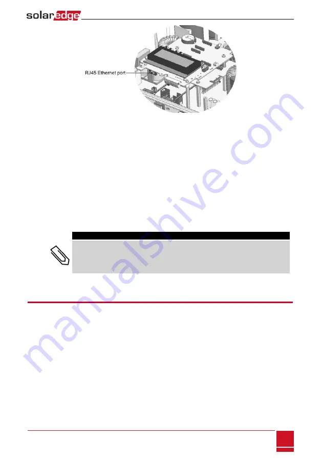
Figure 37: The RJ45 Ethernet connection
7. For the switch/router side, use a pre-crimped cable or use a crimper to prepare an RJ45
communication connector: Insert the eight wires into the RJ45 connector in the same order as above
(
).
8. Connect the cable RJ45 connector to the RJ45 port of the Ethernet switch or router.
You can connect more than one inverter to the same switch/router or to different switches/routers,
as needed. Each inverter sends its monitored data independently to the SolarEdge monitoring
platform.
9. The inverter is configured by default to LAN. If reconfiguration is required:
a. Make sure the ON/OFF switch is OFF.
b. Turn ON the AC to the inverter by turning ON the circuit breaker on the main distribution panel.
c. Use the internal user buttons to configure the connection, as described in
NOTE
If your network has a firewall, you may need to configure it to enable the connection to the
following address:
l
Destination Address: prod.solaredge.com
l
TCP Port: 22222, 22221, or 80 (for incoming and outgoing data)
10. Verify the connection, as described in
Creating an RS485 Bus Connection
The RS485 option enables creating a bus of connected inverters, consisting of up to 31 slave inverters and
1 master inverter. Using this option, inverters are connected to each other in a bus (chain), via their
RS485 connectors. The first and last inverters in the chain must be terminated as described on page 80.
RS485 wiring specifications:
l
Cable type: Min. 3-wire shielded twisted pair (a shielded Ethernet cable (Cat5/5E STP) may be used)
l
Wire cross-section area: 0.2- 1 mm²/ 24-18 AWG (a CAT5 cable may be used)
l
Maximum nodes: 32
l
Maximum distance between first and last devices: 1 km /3300 ft.
Chapter 9: Setting Up Communication to the Monitoring Platform
SolarEdge
-
StorEdge Installation Guide MAN-01-00262-1.3
77
Содержание StorEdge SE7600A-US1
Страница 1: ...SolarEdge StorEdge Solution with Backup Installation Guide For North America Version 1 3 ...
Страница 116: ......


