


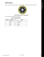


General Details
46
P/N: 1006148-01
Sp
ecification
s
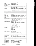
Output Interval for RTCM
Correction Data
1Hz standard
Elevation Mask
0 to 90 degrees (independent of data logging
)
Real-Time Kinematic Mode
Correction Format
f
RTCM SC104 Ver 3.1, 3.0, 2.3, 2.2, or 2.1
CMR/CMR+ (Trimble compatible), TPS proprietary
Supported RTK Network
Solutions
VRS, MAC, FKP
Ambiguity Initialization
On-The-Fly (OTF): L1, L1/L2
Baseline Length
Up to 50km, depending on atmospheric and multipath
conditions
Initialize Time
1 second to 10 min., depending on the baseline length (D) and
multipath conditions
Output Interval for
CMR/RTCM
1Hz standard
Elevation
0 to 90 degrees (independent of data logging)
Solution Mode
Delay (synchronization) mode: 5 to 10 msec
Extrapolation (not synchronized) mode: 10 to 20 msec
Process Interval
1Hz standard; 10, 20, 50 Hz optional
Latency
Delay mode: 5 to 10 msec.
Extrapolation mode: 10 to 20 msec.
Status
Fix, float, DOP, data link status, modem latency, common
satellites
Results
RTK coordinates, HRMS, VRMS
Survey Modes
Base or Rover
Autonomous (standalone)
DGPS (w/ user base)
DGPS (w/ SBAS)
Static
Kinematic (continuous, stop and go)
RTK (delay, extrapolation)
Accuracy (RMS)
g
Static/Fast Static
L1 only:
H: 3mm + 0.8ppm (x D);
V: 5mm + 1.0ppm (x D)
L1+L2:
h
H: 3.0mm + 0.1ppm (x D)
V: 3.5mm + 0.4ppm (x D)
Kinematic, RTK
L1+L2:
H: 8mm + 1.0ppm (x D
)
V: 15mm + 1.0ppm (x D)
Table 8. General Receiver Specifications