


4
Ser
vice
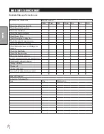
MAINTENANCE
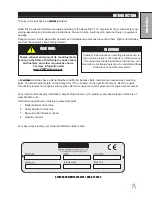
Before servicing or making adjustments to machine, stop engine and remove
key from ignition.
Use all procedures and parts prescribed by the manufacturer's. Read the en-
gine manual before operation.
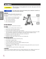
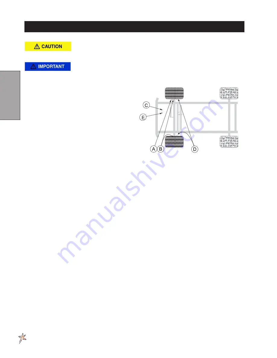
LUBRICATION
Use No. 2 General purpose lithium base grease and
lubricate every 100 hours. The Spray Star 1110 has 7
lube points.
A. One on the rod end of hydraulic cylinder.
B. One on each the right and left spindles.
C. One on the reverse pedal.
D. One on each end of tie rod.
E. One on the forward pedal.
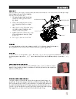
ELECTRICAL CONNECTIONS
Use dielectric grease on all electrical connections.
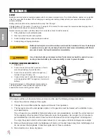
AIR CLEANER
1. Loosen cover retaining snaps and remove cover.
2. Remove pre-cleaner from paper element.
3. Check paper element. Replace element as necessary.
4. Wash pre-cleaner in warm water with detergent. Rinse pre-cleaner thoroughly until all traces of deter
-
gent are eliminated. Squeeze out excess water (do not wring). Allow pre-cleaner to air dry.
5. Saturate pre-cleaner with new engine oil. Squeeze out all excess oil.
6. Reinstall pre-cleaner over paper element.
7. Reinstall air cleaner cover. Secure cover with cover retaining knob.
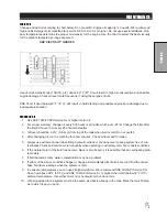
WHEEL MOUNTING PROCEDURE
1. Set park brake. Turn machine off and remove key.
2. Block wheel on opposite corner.
3. Loosen nuts slightly on wheel to be removed.
4. Jack up machine being careful not to damage underside of machine.
5. Place wheel on hub lining up bolt holes.
6. Torque to 64-74 ft/lb (87-100Nm) using a cross pattern. Re-torque after first 8 hours and every 250
hours thereafter.
7. Lower machine to ground and remove blocks and jack.
TIRE PRESSURE
Caution must be used when inflating a low tire to recommended pressure. Over inflating can cause tires to
explode. All tires should be 20 psi (1.4bar). Improper inflation will reduce tire life considerably.
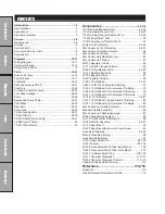
Содержание 10-100-F
Страница 12: ...10 Diagrams WIRING DIAGRAM Use dielectric grease on all electrical connections ...
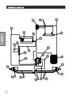
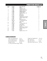
Страница 14: ...12 Diagrams HYDRAULIC DIAGRAM ...
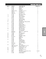
Страница 16: ...14 Parts MAIN BODY DRAWING ...
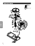
Страница 18: ...16 Parts CONTROL PANEL DRAWING ...
Страница 20: ...18 Parts FRONT AXLE DRAWING ...
Страница 22: ...20 Parts SEAT CONSOLE DRAWING ...
Страница 24: ...22 Parts FUEL TANK DRAWING ...
Страница 26: ...24 Parts OIL TANK OIL FILTER OIL COOLER DRAWING ...
Страница 28: ...26 Parts FOOT PEDAL LINKAGE DRAWING ...
Страница 30: ...28 Parts PUMP DRAWING ...
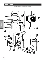
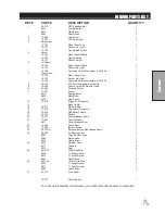
Страница 32: ...30 Parts ENGINE AND SPRAY PUMP DRAWING ...
Страница 34: ...32 Parts PARK BRAKE DRAWING ...
Страница 36: ...34 Parts REAR AXLE DRAWING ...
Страница 38: ...36 Parts TANK DRAWING TURBO QUAD AGITATOR DRAWING ...
Страница 40: ...38 Parts 15 301 ORBITAL DRAWING ...
Страница 42: ...40 Parts 45 373 DDC20 PISTON PUMP DRAWING ...
Страница 54: ...52 Accessories CONTROL MOUNTS ...
Страница 58: ...56 Accessories STAR COMMAND I II DRAWING 15 817 O ring for 50 Series Clamp 15 818 O ring for 75 Series Clamp ...
Страница 61: ...59 Accessories STAR COMMAND I WIRING 10 716 M ...
Страница 66: ...64 Accessories 10 648 3 WAY MANUAL VALVE DRAWING ...
Страница 71: ...69 Accessories NOTES ...
Страница 72: ...70 Accessories 17 585 18 HD BOOM DRAWING ...
Страница 74: ...72 Accessories 17 585 18 HD BOOM DRAWING ...
Страница 80: ...78 Accessories 17 601 15 HD BOOM DRAWING ...
Страница 82: ...80 Accessories 17 601 15 HD BOOM DRAWING ...
Страница 92: ...90 Accessories 16 906 ELECTRIC HOSE REEL DRAWING ...
Страница 96: ...94 Accessories 1102 1104 HOSE REEL PLUMBING DRAWING STAR COMMAND I II HOSE REEL PLUMBING DRAWING ...
Страница 104: ...102 Accessories FOAMER NOZZLE MOUNT DRAWING ...
Страница 106: ...104 Accessories 14 291 FOAMER REPLACEMENT PARTS ...
Страница 112: ...110 Accessories 10 417 CHEMICAL CLEAN LOAD TROUBLE SHOOTING ...
Страница 114: ...112 Accessories 15 620 CHEMICAL CLEAN LOAD DRAWING ...