
109
Accessories
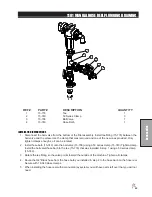
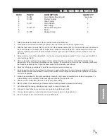
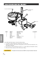
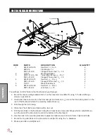
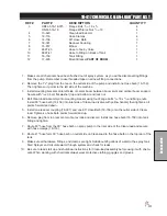
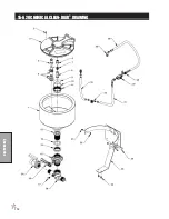
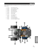
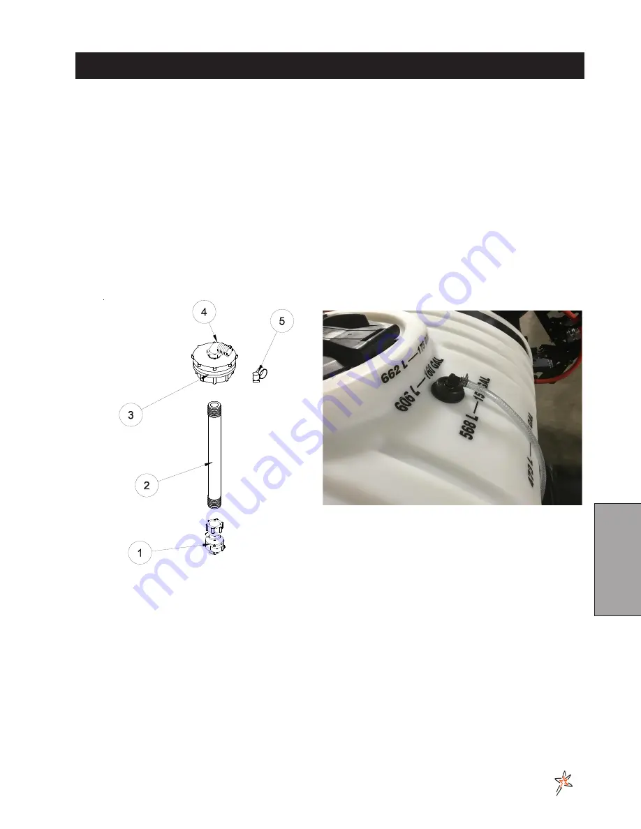
10-734 16 GALLON RINSE TANK
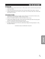
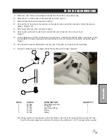
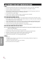
9. With wire cutter. Remove the alligator clamps from the ends of the pump wiring.
10. Strip about 1" on both ends of the black and red wires. Figure 1.
11. Slide on heat shrink and connectors. Figure 2.
12. Connect the 12' red wire to the red wire on the electric pump using the connector. Crimp the wires to
-
gether. FIgure 3 & 4.
13. Slide heat shrink over the connector. Figure 5.
14. Heat in place with just enough heat to melt shrink over connection. Do not over heat.
Figure 6.
15. On the opposite end of the 12' black and red wire place a heat shrink and the slide on connector. Crimp
the connector into place and place the heat shrink over the end of the wire. Heat the shrink into place.
Figure 7.
16. Run the wire below the floorboard to the fuse box. Plug slide on connectors into fuse block.
17. Follow the instructions in the Spray Tanks Owner Manual for proper operation.
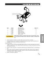
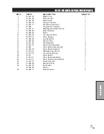
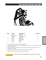
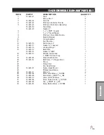
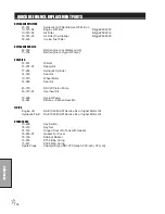
REF# PART#
DESCRIPTION
QUANTITY
1
30-246
Tank Rinsing Nozzle
1
2
30-247
8" Nipple
1
3
33-495
Bulk Head Fitting
1
4
16-937
Elbow
1
5
18-186
Clamp
1
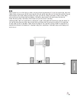
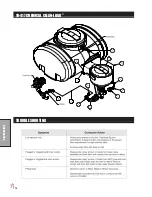
The rinsing system can be placed on any flat surface on the top of the spray tank as long as the hose
from the 16 gallon spray tank will reach the elbow in the bulkhead. 1-5/8 " hole saw will be needed.
Содержание 10-100-F
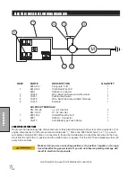
Страница 12: ...10 Diagrams WIRING DIAGRAM Use dielectric grease on all electrical connections ...
Страница 14: ...12 Diagrams HYDRAULIC DIAGRAM ...
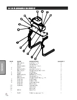
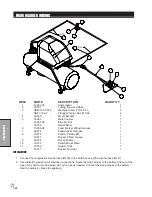
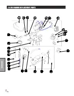
Страница 16: ...14 Parts MAIN BODY DRAWING ...
Страница 18: ...16 Parts CONTROL PANEL DRAWING ...
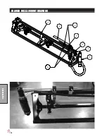
Страница 20: ...18 Parts FRONT AXLE DRAWING ...
Страница 22: ...20 Parts SEAT CONSOLE DRAWING ...
Страница 24: ...22 Parts FUEL TANK DRAWING ...
Страница 26: ...24 Parts OIL TANK OIL FILTER OIL COOLER DRAWING ...
Страница 28: ...26 Parts FOOT PEDAL LINKAGE DRAWING ...
Страница 30: ...28 Parts PUMP DRAWING ...
Страница 32: ...30 Parts ENGINE AND SPRAY PUMP DRAWING ...
Страница 34: ...32 Parts PARK BRAKE DRAWING ...
Страница 36: ...34 Parts REAR AXLE DRAWING ...
Страница 38: ...36 Parts TANK DRAWING TURBO QUAD AGITATOR DRAWING ...
Страница 40: ...38 Parts 15 301 ORBITAL DRAWING ...
Страница 42: ...40 Parts 45 373 DDC20 PISTON PUMP DRAWING ...
Страница 54: ...52 Accessories CONTROL MOUNTS ...
Страница 58: ...56 Accessories STAR COMMAND I II DRAWING 15 817 O ring for 50 Series Clamp 15 818 O ring for 75 Series Clamp ...
Страница 61: ...59 Accessories STAR COMMAND I WIRING 10 716 M ...
Страница 66: ...64 Accessories 10 648 3 WAY MANUAL VALVE DRAWING ...
Страница 71: ...69 Accessories NOTES ...
Страница 72: ...70 Accessories 17 585 18 HD BOOM DRAWING ...
Страница 74: ...72 Accessories 17 585 18 HD BOOM DRAWING ...
Страница 80: ...78 Accessories 17 601 15 HD BOOM DRAWING ...
Страница 82: ...80 Accessories 17 601 15 HD BOOM DRAWING ...
Страница 92: ...90 Accessories 16 906 ELECTRIC HOSE REEL DRAWING ...
Страница 96: ...94 Accessories 1102 1104 HOSE REEL PLUMBING DRAWING STAR COMMAND I II HOSE REEL PLUMBING DRAWING ...
Страница 104: ...102 Accessories FOAMER NOZZLE MOUNT DRAWING ...
Страница 106: ...104 Accessories 14 291 FOAMER REPLACEMENT PARTS ...
Страница 112: ...110 Accessories 10 417 CHEMICAL CLEAN LOAD TROUBLE SHOOTING ...
Страница 114: ...112 Accessories 15 620 CHEMICAL CLEAN LOAD DRAWING ...