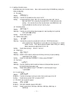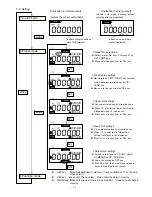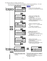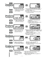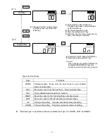
[ For binary output ]
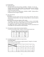
The table below shows correspondence of preset numbers (1 to 31) and output terminals
(OUT 1 to 5) in binary output. A smaller preset number is outputted when outputs are
overlapped. Output form is COMPARE output only and fixed.
(
○
: ON,
×
: OFF)
Output
terminals
Preset No.
1
2
3
4
5
Output
terminals
Preset No.
1
2
3
4
5
1
○
×
×
× ×
17
○
×
×
× ○
2
×
○
×
× ×
18
×
○
×
× ○
3
○
○
×
× ×
19
○
○
×
× ○
4
×
×
○
× ×
20
×
×
○
× ○
5
○
×
○
× ×
21
○
×
○
× ○
6
×
○
○
× ×
22
×
○
○
× ○
7
○
○
○
× ×
23
○
○
○
× ○
8
×
×
×
○ ×
24
×
×
×
○ ○
9
○
×
×
○ ×
25
○
×
×
○ ○
10
×
○
×
○ ×
26
×
○
×
○ ○
11
○
○
×
○ ×
27
○
○
×
○ ○
12
×
×
○
○ ×
28
×
×
○
○ ○
13
○
×
○
○ ×
29
○
×
○
○ ○
14
×
○
○
○ ×
30
×
○
○
○ ○
15
○
○
○
○ ×
31
○
○
○
○ ○
16
×
×
×
× ○
Preset data are represented by combinations of output signals from OUT 1 to 5. When
incoming pulses do not match with any preset numbers, all the outputs (OUT 1 to 5) are
turned OFF. Reading OK signal is cylinder stop output. Binary output is only active when
a cylinder is at stop. Reading outputs by PLC/ PC shall be done only when cylinder stop
output is ON. Preset values can be stored up to 31 points. However, No. 21 to 31 are
only active in binary output and their preset output form is fixed at "COMPARE" mode.
7-3-5. Output
(1) Output form can be set to preset data No. 1 through 31 (However, No. 21 to 31 are
only active in binary output and their preset output form is "COMPARE" only).
(2) In normal output, indication in LCD corresponding to “OUT 1 to 5” changes from “_” to
“
□
” in preset output.
(3) With upper or lower limit, if the preset data including lower limit (point A in the next
page) or upper limit (point B in the next page) exceeds
-
999999 or + 999999, point A or
B will be compulsorily corrected to the range of
-
999999 to + 999999.
(4) Refer to “Output timing chart” in the following page for time of output delay.
!
Caution
With preset data set to zero, take ample care for preset output at turning ON the power.
-
22
-


