Chapter 6: Wiring
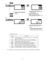
6-1. Terminal block arrangement
A
B
COM
DC12
V
240VAC
VDC (-)
COM
100 -
(+) 24
GND
F.G.
RESET HOLD
BANK1
COM
BANK2
COM OUT1
OUT5
OUT4
OUT3
OUT2
S
.
STOP
RD
SG
SD
(UP
p
u
ls
e
)
B
-phas
e pul
s
e
input
S
ens
or
i
nput
co
m
m
o
n
Sens
or
power
output
S
ens
or
i
nput
co
m
m
o
n
Sens
or
power
GN
D
FG
t
e
rmi
n
a
l
Res
e
t input
Hold input
Contr
ol input
co
m
m
o
n
B
ank
1
s
elec
ti
on
B
ank
2
s
elec
ti
on
Power
input
ter
m
inals
O
u
tput s
igna
l
co
m
m
o
n
O
u
tput ter
m
inal 1
O
u
tput ter
m
inal 2
O
u
tput ter
m
inal 3
O
u
tput ter
m
inal 4
O
u
tput ter
m
inal 5
Cy
linder
s
top
output
Se
ri
a
l
tr
an
s
mis
s
ion
Sensor input block
(connect to Monosashi-kun or encoder)
Control input block
(input control signals)
Counter
power
supply
Output block (terminals for preset output and
cylinder stop output)
Serial transmission block
(terminals for RS-232C
communication)
A
-phas
e pul
s
e
input
(D
O
W
N puls
e)
!
Caution
The COM terminal of each block is insulated from COM terminals of other blocks
(However, COM terminal and GND terminal in sensor input block are connected inside).
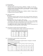
6-2. Wiring of sensor input part
Change the wiring combination of white-A/blue-COM and yellow-B/brown-COM like white-B/blue-COM
and yellow-A/brown-COM in pair to reverse the count direction.
(
)
1 kΩ
(
)
+12V
+12V
6 8 0 Ω
B u ilt-in se n so r p ow e r
sup p ly
1 2V D C , 6 0 m A
A
B
C O M
C O M
+12V
G N D
F .G .
C E U 5 se n so r in p u t p a rt
S M C M o n o sa s h i-k u n s e rie s
W h ite
B lu e
Y e llo w
B ro w n
R e d
B la ck
1 kΩ
+12V
+12V
6 8 0 Ω
!
Caution
Wire colors are for SMC Monosashi-kun series. For other encoders, check the wiring
specified in encoder operation manual.
-
11
-


