


Electrical Connection of the Sunny Backup 2200
SMA Solar Technology AG
66
SBU2200-TEN083320
Technical Description
P
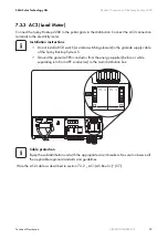
roceed as follows when installing the relay connections:
1. Pierce the rubber plug with a pin-
shaped object.
2. Attach cable end sleeves to the
conductors.
3. Route both conductors through the
opening from the outside.
4. Insert the wires into the "Relay1" or
"Relay2" connection terminals of the
3- pole print terminals included in the
delivery.
5. Tighten the screws of the connection
terminals.
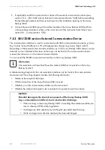
6. Note how the pins are labeled:
– NC: Normally closed (closed
when in standby)
– C: Contact (operating contact)
– NO: Normally opened (open
when in standby)
7. Push the 3-pole print terminal into the appropriate socket.
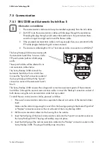
Load Shedding
The Sunny Backup 2200 can automatically switch off loads to protect the battery from deep
discharge. To do so, an external (AC or DC) power contactor must be installed between the Sunny
Backup 2200 and the loads (see also section 22.1 „Accessories (Optional)“ (162)).
Function of the relay
You can only assign one function to each relay.
Switching processes of the relay
Information on the switching capacities of the relays is provided in section 23 „Technical
Data“ (163).
NOTICE!
The loads are no longer supplied.
If a relay is used for load shedding, the loads connected to the load breaker will no longer
be supplied with electricity in the event of a fault in the Sunny Backup System S. This occurs
even if grid power is available.
NC
NO
C


