background image

NOTICE SM CRIMP 2000-V8.0 / Mai 2012


17


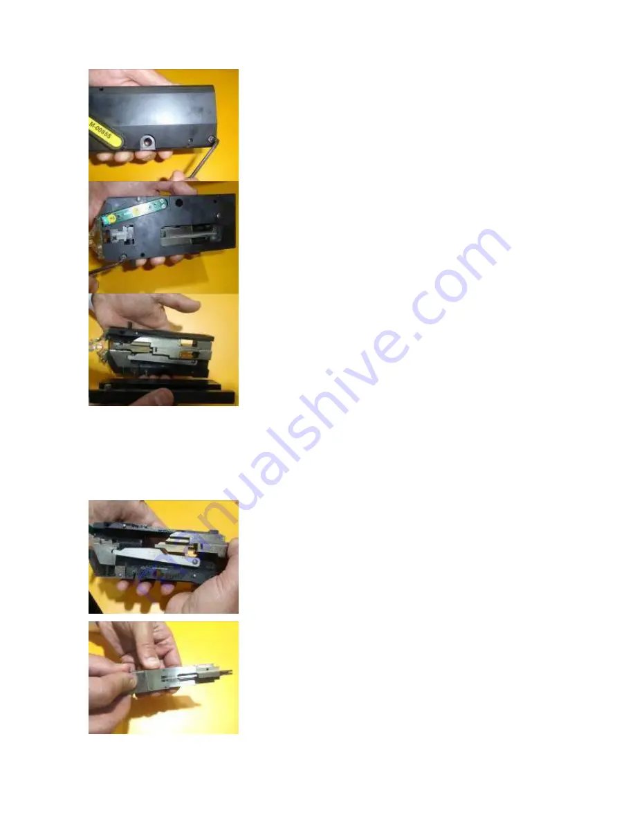
Remove  the  front  screw  on  the  cover  of  the 
tooling. 


Remove  the  screw  located  on  the  rear  of  the 
tooling. 


Slowly open the cover of the tooling. 


Place all of the components on a clean surface. 


5.2


 Replacing the punch and/or the guide 

To dismantle the tooling, refer to chapter 5.1 


Holding  the  tooling  in  your  left  hand,  you  must 
now check that the sliders can easily slide up and 
down simultaneity.  


Do  not  turn  the  tooling;  avoid  any  damage  on 
cutting-block and anvil. 


Separate  the  punch  slider  from  the  punch-guide 
slider  by  rotating  the  punch  slider  as  shown  on 
the picture. 


Ensure  that  the  punch  pin  does  not  fall  on  the 
floor. 

Содержание SM CRIMP 2000

Страница 1: ...2000 V7 5 July 2010 1 SM CRIMP 2000 Operators Manual SM CONTACT ZAC de la Bonne Rencontre 20 à 22 Voie Gallo Romaine 77860 QUINCY VOISINS Tel 00 33 01 64 63 66 66 Fax 00 33 01 64 63 67 22 E mail smcontact smcontact fr ...

Страница 2: ...hase motor with worm gear Stroke 35 mm Crimping rate Up to 4 000 strokes h Motor power 0 25kW Supply voltage 110V or 230 V single phase Power consumption 2 A Power frequency 50 Hz Sound level 75 db A Dimensions W 291 x H 340 x D 490 mm Weight 59 kg with tool cassette ...

Страница 3: ...punch and or the guide 17 5 3 Replacing the anvil 19 5 4 Replacing the cutting block 20 5 6 Setting up the cutting block 22 5 7 The slice stop 22 5 8 Replacing and centring the clincher 23 6 THE tooling STORAGE DEVICE 25 6 1 View and data modifications of the technical datasheet 25 6 2 Updating the data of the technical sheet into the memory 27 7 DISMANTLING AND REASSEMBLING 28 7 1 The frontal com...

Страница 4: ...f the machine and all sensitive details He is responsible for the further training of his personnel Any person involved with the operation maintenance repair or inspection of the crimping press at the user s premises must have read and understood the Operating Instructions and in particular this Section on Safety The responsibilities relating to operation of the machine must be clearly stipulated ...

Страница 5: ...e caught in the clincher should not be removed before the machine has been switched off The machine must always be switched off before changing the splice band reel Switch off the machine before any intervention into the machine and when changing the tooling Only qualified personnel should perform adjustment and maintenance operations See Sections 8 for transportation of the machine either manuall...

Страница 6: ... operated with the safety devices on 2 Never extend your hands into the danger area 3 Should a fault or an accident occur immediately press the E Stop Emergency button and disconnect the power cable 3 2 Power connection Only qualified personnel must perform any work on the electrical system such as connection to power maintenance or repairs Even with the Emergency Stop button pressed parts of the ...

Страница 7: ...onnect power cable K Connect foot pedal cable P Turn on the main switch N if the switch is in the off position lamp not lit the machine is not live Unlock Emergency Stop button by turning it to the right Main Switch module The machine is ready K K K P N 2 x fuses ...

Страница 8: ...ed but the cycle does not start The following functions can be regulated with 4 buttons on the front of the machine 3 4 1 The key MODE From the main screen display access those following functions Quantity 150 Total quantity 439870 123456789 123456789 Show the normal operating state of the machine The figures highlighted on the first line show the inputs activities The figures highlighted on the s...

Страница 9: ...he language French English German Spanish Italian Japanese Chinese or Korean Press the key MODE to confirm the selection Cassette SM CRIMP Use the key and to scroll the tooling technical data Components to crimp spare parts crimping height pull force type of splice Enter the access code 0000 Restricted to manufacturer Please be aware that the soft version noted on this view is only indicative info...

Страница 10: ...the feeding system In the others displays the keys and allow you to scroll the menu options 3 5 Splice band feeding system How to install a new reel and to introduce the banding Position the splice banding reel vertically Remove the safety film Install the reel onto the shaft The tag with the reference must be facing the operator Unwind the ribbon Cut off the bent section of banding Position the b...

Страница 11: ...ollers If the banding is not straight cut it with cutting pliers Under no circumstances should the banding be distorted this will cause a feeding problem The banding should not be bent when inserted into the tooling While holding the banding at the entrance of the cutting block press key Keep pressing the key until the feeding motor system stops automatically The banding must form a curve toward t...

Страница 12: ... clincher and clincher holder This ensures that all the parts of the upper tool have taken their correct position 3 6 1 Centring the clincher This operation must be done without splice band and lamp light Place the clincher and clincher holder back on the machine Using the hand wheel bring the punch down slowly until the punch is in middle of the clincher Be careful if the punch is not correctly p...

Страница 13: ...cal datasheet Before putting the machine into production it is advised to verify if the dimensions of the connections are compatible with our recommendations Refer to the technical data sheet and check the information The tooling can also be delivered independently from the machine This can have the obligation updating the information under advice set up with the customer s technical datasheet E5 ...

Страница 14: ...e only with the index pin Press the key and remove the banding from the tooling Next press the Emergency Stop switch button DISMANTLING Unscrew the clincher holder In order to not damage the finger guard pull the clincher holder forward Remove the tooling mounting screw Remove the tooling 1 2 3 4 5 ...

Страница 15: ... introduce both centring pins The instantaneous contact of the tooling with the machine must make a clear CLICK This metallic sound indicates that both surfaces are perfectly in contact with each other Tighten the tooling mounting screw Ensure that the clincher mounting surface is perfectly clean and has no conductors or insulation residues adhering to it In order prevent damaging to the finger sa...

Страница 16: ... the tooling 5 1 Opening the tooling Place the tooling onto a clean surface When handling the tooling be careful not to damage the finger guard Loosen the screw of the cutting block The screw should be placed 8 to 10 mm above the face of the tooling Push the cutting block slightly sideways with small screwdriver Contact sonde 1 K K 1 ...

Страница 17: ...2 Replacing the punch and or the guide To dismantle the tooling refer to chapter 5 1 Holding the tooling in your left hand you must now check that the sliders can easily slide up and down simultaneity Do not turn the tooling avoid any damage on cutting block and anvil Separate the punch slider from the punch guide slider by rotating the punch slider as shown on the picture Ensure that the punch pi...

Страница 18: ...stalled Before tightening the screw be sure that punch guide is facing upward Introduce the punch at the guide extremity Do not grease the punch Only punches for 4mm splice profiles are symmetrical punches for 2 and 6mm splice profiles have an offset hole In the case of 2 or 6mm punch the hole must be placed close to the slider body Grease the punch and guide slider face no grease on the punch and...

Страница 19: ... slide up and down inside it To do this take a screwdriver and first push the punch guide slider and then the punch slider up and down The punch slider is difficult to move because it is pressing the anvil sideways This resistance is normal Undo the old anvil Clean the anvil using a degreaser Lubricate both faces of the anvil Lubricate the anvil spring Place the new anvil Before re assembling clea...

Страница 20: ...inside it To do this take a screwdriver and firstly push the punch guide slider and then the punch slider up and down The punch slider is difficult to move because it is pressing the anvil sideways This resistance is normal Remove the anvil By pushing behind slightly slide the cutting block Clean up the cutting block location with degreaser Replace the anvil Before re assembling clean up every par...

Страница 21: ... guide and punch sliders as indicated on the picture Please check that there are no residues left Place the tooling cover and screw the support Once the tooling is closed check the guide slider and the punch slider To do so introduce a screw driver as indicated in the picture and push up and down You should not have any restrains in the sliding ...

Страница 22: ...he lower part Press firmly the cutting block against the guide Tighten the pressure screw until full compression of the spring Don t over compress the spring 5 7 The slice stop Remove the stop splice screw Move back the stop splice in order to move it away from the guide Tighten slightly and stop if you get any resistance ...

Страница 23: ...the clincher Undo the clincher screw of the clincher holder Slide the clincher toward yourself in order to remove it from the holder Check if there are no residues left Release the screw with a 13mm wrench While changing the clincher check that the data are similar into the set up system and SM Contact To do so refer to the technical datasheet ...

Страница 24: ...lace The clincher should be able to move into the clincher holder If not you need to replace the clincher holder Using the hand wheel cycle the press manually until the punch reaches the centring of the clincher Continue to slowly turn the hand wheel while monitoring the movement of the punch downwards from the side Stop rotating the wheel when you hear a BIP noise Lift up the alphabetical indicat...

Страница 25: ...al datasheet of the tooling When setting up the tooling the data is automatically transferred in the electronically card of the machine This function allows transferring quickly the different set up parameters to the spare parts listing to the pulling force that you should obtain in the connection 6 1 View and data modifications of the technical datasheet The transferred data into the storage devi...

Страница 26: ...t we can send you the updated version of the technical datasheet This allows us to follow the evolution of the tooling The folder that you receive is named SMCRIMP xls Do not rename the folder as the machine only recognizes the SM CRIMP name Once the alterations have been made use the function save as ...

Страница 27: ...information related to your tooling In case of parameters modifications please send your folder SMCRIMP xls to smcontact smcontact fr 6 2 Updating the data of the technical sheet into the memory Copy the folder SMCRIMP xls into a USB key Put the machine under sub voltage The screen display must show quantity The tooling must be on the machine when proceeding to data transfer On the machine right i...

Страница 28: ... AND REASSEMBLING 7 1 The frontal compartment If more space is required for crimping larger components the front compartment can be removed This is secured by two screws behind the blue plastic box After removing the compartment place the two screws back in the holes so that they do not get misplaced 7 2 The right hand safety cover Remove the wheel ...

Страница 29: ...NOTICE SM CRIMP 2000 V8 0 Mai 2012 29 Remove the 4 screws 7 3 The left hand safety cover Remove the 4 screws 7 4 The front panel Remove the lower screw Undo the screw on the top left side ...

Страница 30: ...NOTICE SM CRIMP 2000 V8 0 Mai 2012 30 FOOT PEDALE POWER FORK SENSOR USB CONNECTOR RIBBON ADVANCE MOTOR DRIVER EMERGENCY STOP 4 5 1 2 3 6 7 POTENTIOMETER 1 2 3 5 6 7 8 8 4 ...

Страница 31: ...ty cover Unscrew the two support screws of the belt bracket tension pulley Remove the tension pulley bracket Remove the belt Put a 243 Loctite drop on the screw threads on the machine Prepare the two screws with tension washers Brace pulley Roller Motor Pulley Belt Tool yoke pulley Tool yoke tensioner ...

Страница 32: ...ure and without turning the belt over verify the following view The mark position should be as indicated in the picture Place the red mark onto the brace pulley mark Do not change the brace pulley s position Place the pulley mark onto the pulley motor Terminate positioning operations by placing the belt marker into the belt bracket pulley tensioner ...

Страница 33: ...l yoke while turning with the hand wheel As long as the belt rounded tighten the tool yoke When the rounded shape disappears turn an additional turn Do manually several cycles and verify that the belt is correctly stretched 7 6 The gear motor Unplug the power cable Remove the right cover Dismantle the belt and the tension pulley bracket Remove the cable of the cable clamp Remove cable of the alumi...

Страница 34: ...et on the USB key 7 8 List of inputs and outputs 7 8 1 Inputs 1 IN1 n a 2 SWRUB band contact 3 PEDAL1 pedal n 1 4 PEDAL2 pedal n 2 5 BP_SECU Emergency stop 6 PIN Pin position 7 CONTROL crimping validation 8 OUTIL1 n a 9 OUTIL2 n a 7 8 2 Outputs 1 READY ready to crimp 2 FINCYC end of crimping cycle 3 RSTVAR reset convertor 4 FWDVAR convertor controller 5 BKL lamp light 6 LUM lamp 7 BUZZER resoundin...

Страница 35: ...e of the lights switch on No power cable Make sure the power is on The fuses are faulty Verify the fuses The screen display is blank The electronic card is on sub voltage Verify the 12V voltage chap 7 4 Potentiometer of luminosity Readjustment of the Potentiometer Electronic card out of order Replacement of the carte The machine stops too far Convertor speed too quick Reduce the speed chap 9 4 The...

Страница 36: ...band on the machine chap 3 5 The Band is hitting in the transport carriage Replace the splice band The tool contact touch point is broken Chapter 5 1 The ribbon skates in the reel of the feeding system Replace the splice band The belt jumps The tool yoke is broken Replace the engin roller Replace the presseur roller Replace the tool yoke chapter 7 5 The tool yoke is not stretched Re tighten the be...

Страница 37: ...isfactory re adjust the clincher centring This re adjustment is likely to be necessary after 1000 crimps in particular if the cassette has been dismantled See Section 5 8 9 2 Punch guide colliding or too far from the top of the clincher If the two parts are too far from each other at the lower dead centring position the splice may not correctly formed may break or one side of the splice will be fo...

Страница 38: ...ed Clincher worn Punch worn or broken Note The side edges at the tip of the punch seen from below must be sharp and symmetrical If the punch is small it may be necessary to use a magnifying glass to observe the tip Guide leveL spring GUIDE LEVER HEIGHT ADJUSTMENT Edges worn or broken Edges on both sides straight and flat Punch bad Punch good ...

Страница 39: ...your name telephone and fax number machine and tooling number 9 4 Display is showing error index the pin The engine runs too fast and exceeds the top dead center before stopping Reduce the speed of the frequency The engine is running too slowly and stops before the top dead center Increase the speed of the frequency The speed controller display indicates the speed of the motor in hertz Note When t...

Отзывы: