4. Installation instructions
page 23
EN
Installation holes for the attachment of the oil + air
lubrication system to the wall must be made in
accordance with the stipulations of the section
'Mounting dimensions'.
Caution!
During installation work - and particu-
larly when drilling - the following points
must be observed:
)
Existing supply lines must not be
damaged by the installation work.
)
Other units must not be damaged
by the installation work.
)
The oil + air lubrication system
must not be mounted within the
radius of activity of moving parts so
it will not interfere with or be stuck
by moving parts.
)
The oil + air lubrication system
must be installed a sufficient dis-
tance away from sources of heat,
so that the maximum ambient
temperature of 40°C is not ex-
ceeded.
)
Country specific installation and
accident prevention regulations
must be observed.
4.2 Mounting dimensions
Oil + air lubrication systems are intended for wall
mounting. They are attached to the intended
mounting location using appropriate fastening
materials (e.g., bolts, washers, and nuts).
For the dimensions and location of the fixing holes,
see the documentation of the oil + air lubrication
system. If no documentation is available, the di-
mensions and location of the fixing holes for
mounting the unit can be determined by taking
measurements.
If no documentation is available, you can
directly request the documentation from
SKF Lubrication Systems Germany
GmbH.
4.3 Electrical connection
4.3.1 Electrical connection motor
In the standard design, oil + air lubrication systems
contain compact units. Compact units are driven by
electric motors. The electric motors are capacitor
motors designed for 115 / 230 V 50 / 60 Hz
single-phase alternating current.
Danger!
Electrical connections for the compact
unit may only be established by qualified
and trained personnel authorized to do
so by the operator. The local conditions
for connections and local regulations
(e.g., DIN, VDE) must be strictly ob-
served. Significant bodily injury and
property damage may result from an
improperly connected compact unit.
In the basic oil + air lubrication system design
without a control unit, the electrical connection to
the motor is established using a rectangular con-
nector as per DIN EN 175301-803-A (clamping
range Ø 8 - 10 mm). In the basic design with a
control unit, the motor is connected to the elec-
tronic control unit.
Содержание OLA Series
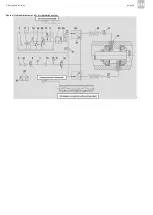
Страница 19: ...3 Design and function page 19 EN Figure 4 Hydraulic diagram of oil air lubrication system ...
Страница 37: ...6 Operation page 37 EN Oil air Exhaust air Figure 7 Lubricant delivery on various types of ball bearings ...
Страница 49: ...blank page ...
Страница 50: ...blank page ...
Страница 51: ...blank page ...

