4. Installation instructions
page 28
EN
4.6 Lubrication line connection
The main lubricant line connecting the compact
unit with the oil + air metering unit is already
installed on oil + air lubrication systems.
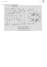
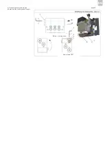
Install the lubrication point line(s) as shown in
Figure 5.
The lubrication point line leading from the oil + air
metering unit to the lubrication point must be
connected to the oil + air lubrication system in such
a way that no forces can be transferred to the
assembled oil + air lubrication system (stress-free
connection).
Lubrication point lines made of transparent plastic
are recommended so that the lubricant transport
in the lubrication point lines (oil streak formation)
can be assessed visually. The requirements for the
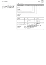
lubrication point lines are summarized in Table 4.
Table 4: Requirements for lubrication point
lines
Lubrication point lines made of transparent plastic
are available in rigid (unplasticized) and flexible
(plasticized) designs with the following order num-
bers (please indicate requested length):
Rigid plastic tubing:
WVN715-RO4X0.85
Flexible plastic tubing:
WVN716-RO4X0.85
The connection for the lubrication point line is
designed as an M8x1 pipe thread with a counter-
bore for a solderless pipe union per
DIN 3854/DIN 3862 for pipe Ø 4 mm. The follow-
ing fittings are required to install the lubrication
point line:
Lubrication point line, plastic tubing Ø 4 mm:
404-603 Reinforcing socket
404-611 Tapered sleeve
404-612 Socket union
The lubrication point lines can be laid in a rising or
falling position. A hose coil (30) is installed approx.
0.3 m in front of the nozzle (32) and serves as a
lubricant reservoir. After the compressed air is
switched off, the lubricant distributed in the hose
coil collects in the lower bends of the coil. This
ensures that the bearing is quickly supplied with
lubricant once the compressed air is switched on
again. The center line of the hose coil should be
laid horizontally or inclined at a max. angle of 30°.
Avoid changes in the cross-section of the lubrica-
tion point line from small to large cross-sections in
the direction of flow. When the cross-section does
change, the transition should be gradual.
SKF oil-streak sensors are recommended for
monitoring a continuous lubricant flow in the
lubrication point lines. Oil-streak sensors allow
monitoring of the transport of the oil streak along
the wall of the lubrication line between the oil + air
metering unit or the mixing valve and the lubrica-
tion point.
Order number for oil-streak sensor:
GS4011-S20 for lubrication point line
Ø 4 mm
GS6011-S20 for lubrication point line
Ø 6 mm
Requirement
Values
Minimum length to hose coil
1 m
Maximum length to hose coil
10 m
Recommended lubrication
point line
- WVN715-RO4X0.85
- WVN716- RO4X0.85
Ø 4 x 0.85 mm
(wall thickness)
Содержание OLA Series
Страница 19: ...3 Design and function page 19 EN Figure 4 Hydraulic diagram of oil air lubrication system ...
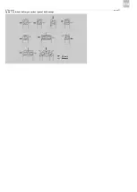
Страница 37: ...6 Operation page 37 EN Oil air Exhaust air Figure 7 Lubricant delivery on various types of ball bearings ...
Страница 49: ...blank page ...
Страница 50: ...blank page ...
Страница 51: ...blank page ...

