4. Installation instructions
page 27
EN
4.5 Compressed air line connection
The compressed air line must be connected to the
oil + air lubrication system in such a way that no
forces can be transferred to the assembled oil + air
lubrication system (stress-free connection).
Danger!
Before connecting the oil + air lubrica-
tion system to the compressed air sup-
ply, make sure that the main air valve is
closed.
Caution!
The specified minimum primary air
pressure for operating the oil + air lu-
brication system must be maintained.
The compressed air must be dry and filtered. A
water separator, preferably with semi-automatic
drainage, is recommended for the preparation of
compressed air.
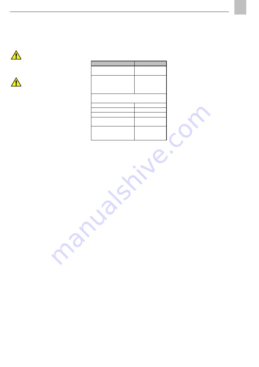
Detailed requirements for the compressed air are
listed in Table 3. The following applies regarding
the air volume required:
Higher-viscosity lubricant requires a larger volume
of air to transport the oil streak in the lubrication
point line.
Larger air volumes must be provided due to the
greater adhesion of high-viscosity lubricants to the
wall of the lubrication point line.
The compressed air to be used must comply with
at least quality class 3 as defined by DIN ISO
8573-1:
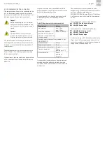
Table 3: Requirements for compressed air
Compressed air preparation can be optimized and
machine downtime and high maintenance costs
avoided by using compressed air of the appropriate
quality class.
The connection for the compressed air line is
designed as an M10x1 pipe thread with a counter-
bore for a solderless pipe union per
DIN 3854/DIN 3862 for pipe Ø 6 mm. The follow-
ing fittings are required to install the compressed
air line:
Compressed air line, metal tubing Ø 6 mm:
406-001 Double tapered sleeve
406-002 Socket union
Compressed air line, plastic tubing Ø 6 mm:
406-603 Reinforcing socket
406-611 Tapered sleeve
406-612 Socket union
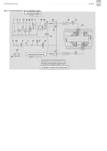
A switch valve, e.g., a 3/2 directional control valve
(Fig. 4, item 24), is recommended in the air inlet
line for compressed air so that the compressed air
supply can be switched on and off.
Requirement
Values
Inlet pressure
min. 3 bar
max. 10 bar
Air volume required
(line with 2.3 mm internal
diameter, recommended oil
viscosity range)
1000 - 1500 l/h
Based on quality classes of compressed air per
DIN ISO 8573-1
Particle content
Class 3
Maximum particle size
5 µm
Maximum particle content
5 mg/m³
Pressure dew point
Class 4
maximum: +3 °C
Oil concentration
Class 3
maximum:
1 mg/m³
Содержание OLA Series
Страница 19: ...3 Design and function page 19 EN Figure 4 Hydraulic diagram of oil air lubrication system ...
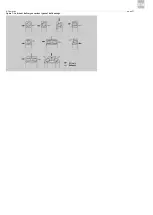
Страница 37: ...6 Operation page 37 EN Oil air Exhaust air Figure 7 Lubricant delivery on various types of ball bearings ...
Страница 49: ...blank page ...
Страница 50: ...blank page ...
Страница 51: ...blank page ...

