6. Operation
page 39
EN
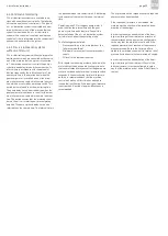
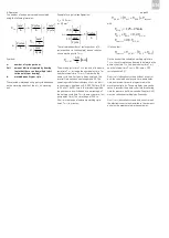
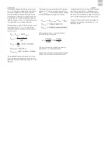
The number of pulses per second is calculated
using the following formulas:
Symbols:
n:
number of cycles per hour
Voil:
amount lubricant required by bearing
(note that there can be multiple lubri-
cation points per bearing)
d:
metered quantity per cycle
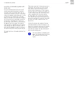
The selected metered quantity per cycle d depends
on the metering volume of the oil + air metering
unit.
Example for a typical configuration:
V
oil
= 150 mm
3
d = 30 mm
3
The calculated number of cycles per hour n (5
cycles per hour in this example) is used to deter-
mine a working cycle T
WC,S3
.
The working cycle time T
WC,S3
consists of the pump
cycle time T
PCT
, including the pump delay time T
PDT
and the interval time T
INTERVAL
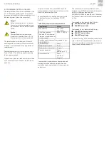
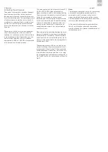
. Now, derive the
pump cycle time (incl. pump delay time) and the
interval time based on operating mode S3. The
operating mode for basic designs of oil + air lubri-
cation systems is defined as S3, 20% ON-time (1.25
to 25 min). The ON-time is the time during which
the gear pump is switched on as a percentage of
the working cycle time T
WC,S3
(pump cycle time, incl.
pump delay time). The time range of 1.25 to
25 min is the range of selectable working cycle
times T
WC,S3
in minutes.
with
It follows that:
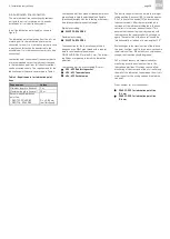
On the basis of the calculated working cycle time
T
WC,S3
, these formulas can be used to determine the
pump cycle time T
PCT
(incl. pump delay time T
PDT
)
and the interval time T
INTERVAL
(ON-time = 20%
corresponds to 0.2).
On oil + air lubrication systems without a control
unit, the calculated pump cycle time, pump delay
time and interval time are programmed in the
machine control unit. The pump delay time can be
set as 5 seconds; the pump cycle time (monitoring
time for pressure build-up; see also Chapter 4.4.1)
must be reduced accordingly by 5 seconds.
On oil + air lubrication systems with a control unit,
the electronic control unit installed in the compact
unit must be programmed in the same way.
Cycle
mm
d
h
Cycles
n
h
mm
V
oil
3
3
Cycle
mm
d
h
mm
V
h
Cycles
n
oil
3
3
h
Cycles
Cycle
mm
h
mm
n
5
30
150
3
3
min
60
3
,
n
T
S
WC
Inter va l
PDT
PCT
S
WC
T
T
T
T
3
,
3
,
3
,
3
,
8
,
0
2
,
0
min
25
...
25
,
1
S
WC
Inter va l
S
WC
PDT
PCT
S
WC
T
T
T
T
T
T
PDT
PCT
S
WC
Inter va l
T
T
T
T
3
,
Содержание OLA Series
Страница 19: ...3 Design and function page 19 EN Figure 4 Hydraulic diagram of oil air lubrication system ...
Страница 37: ...6 Operation page 37 EN Oil air Exhaust air Figure 7 Lubricant delivery on various types of ball bearings ...
Страница 49: ...blank page ...
Страница 50: ...blank page ...
Страница 51: ...blank page ...

