4. Installation instructions
page 31
EN
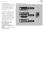
4.8 Venting oil+air mixing valves
MV20x-20
Danger!
Depressurize the oil+air lubrication unit
before starting work.
The mixing valve must be vented during initial
operation, when modifying or replacing it or its
metering units. Note that only the Service
department of SKF Lubrication Systems Germany
GmbH may change the metering units for 10 mm³
and 20 mm³. Larger metering units can also be
changed by the customer under its own
responsibility. The metering unit/mixing valve must
be vented in all cases.
To simplify the venting process, the mixing valve
must be removed from the mounting plate. In
mounted position, the metering units are located
on the bottom of the mixing valve.
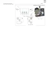
Venting the main oil duct
• Place an oil receive
r tank (supplied by customer)
under the mixing valve. Collect leaking oil with
appropriate agents.
• Depressurize the oil+air lubrication device.
• Separate the compressed air feed (marked Air)
from the mixing valve (1).
• Remove the mixing valve (1) fr
om the mounting
plate (2).
• Remove the screw plug (3) (marked Oil) on the
opposite side of the main oil port.
• Switch on the pump and allow it run until it
pumps oil.
The oil now enters the mixing valve through the
main oil port and discharges on the opposite side.
• Allow the pump to run until oil without bubbles
discharges.
• Close the borehole on the main oil duct again
with the screw plug (3).
• Shut off the pump.
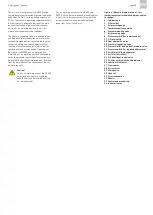
Venting the metering units
• Rotate the mixing valve upwards to enable the
air contained therein to escape.
• Apply the hexagon wrench (WAF 2) to the
threaded pin (4) of the 1st metering unit (5).
• Remove the threaded pins (6) and balls (7) from
the metering units (5).
• Repeat the process on all metering units.
• Let the pump ru
n in intermittent (temporarily
pausing) operation until oil without bubbles
discharges from all metering units.
In the relief phases, the pressure in the oil line
must fall to < 1.5 bar.
After bubble-free oil discharges at all metering
units, switch off the pump and close the metering
units again using the respective balls and threaded
pins.
• Insert balls (7) and threaded pins (6) into the
respective metering units (5).
• Use the hexagon wrench to tighten the threaded
pin (6) with a torque of 1,5Nm.
•
Reinstall the mixing valve (1) on the mounting
plate (2).
Содержание OLA Series
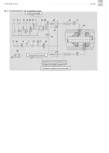
Страница 19: ...3 Design and function page 19 EN Figure 4 Hydraulic diagram of oil air lubrication system ...
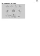
Страница 37: ...6 Operation page 37 EN Oil air Exhaust air Figure 7 Lubricant delivery on various types of ball bearings ...
Страница 49: ...blank page ...
Страница 50: ...blank page ...
Страница 51: ...blank page ...

