


P70
表
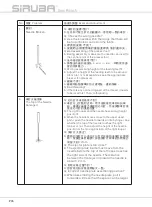
2/Table2
-58-
A
B
C
2.When remove the presser bard, because the
sensor and the induced plate could
not respond to each other and the light of
the sensor is extinguished and the digit
“0” on the panel is still. At that time, the
safety mechanism is activated; the sewing
would not start by pedaling and the operator
is away from the danger when pedaling
accidently.
(
Fig.53)
2.
移 除 押 具 桿 時 , 因 感 測 器 與 感 應 片
感 測 對 應 不 到 , 感 測 器 呈 現 燈 滅
的 狀 態 , 且 操 作 盒 上 之 數 字
”0”
為 靜 止
狀 態 , 此 時 , 電 控 箱 已 啟 動 保 護 機 制 ,
踩 腳 踏 板 不 會 有 車 縫 動 作 , 操 作 者 不
會 因 勿 踩 腳 踏 板 而 發 生 危 險 。(圖
53)
The adjustment of the presser safety
sensor:(Fig.52)
(1) Turn on the power of the sewing machine, if
the correspondence between the indicator-
light on the presser safe sensor and
sensing plate works normally, the
indicator-light on the presser safe sensor
would remain lit. If removing the presser
rod, the indicator-light on the presser safe
sensor cannot sense correspondingly to
the sensing plate , so the indicator-light of
the presser safe sensor would go out. As
a result, the safety system would be
activated by the power control box. Thus, no
sewing performed by pres sing the pedal
and the function is for protecting the
operators not to be in danger by pressing
the pedal accidently.
(2) Turn on the power of the sewing machine;
the presser bar should be on the normal
sewing position. If the correspondence
between the indicator-light on the
presser safe sensor and sensing plate
works abnormally, the indicator-light of the
押 具 安 全 感 測 器 調 整
: (
圖
52)
(1)
打 開 縫 紉 機 電 源 , 若 押 具 安 全 感 測 器
之 檢 測 燈 與 感 應 片 感 測 對 應 正 常 ,
此 時 , 押 具 安 全 感 測 器 電 源 指 示 燈 為 恆
亮 狀 態 , 若 移 除 押 具 桿 時 , 因 押 具 安 全 感
測 器 上 之 檢 測 燈 與 感 應 片 感 測 對 應
不 到 , 押 具 安 全 感 測 器 檢 測 燈 呈 現 滅 的
狀 態 , 此 時 , 已 由 電 控 箱 啟 動 保 護 機 制 ,
若 踩 腳 踏 板 不 會 有 車 縫 動 作 , 此 功 能 為 保
護 操 作 者 不 會 因 勿 踩 腳 踏 板 而 發 生 危 險 。
(2)
打 開 縫 紉 機 電 源 , 押 具 桿 於 正 常 車 縫
位 置 , 若 押 具 安 全 感 測 器 檢 測 燈 與 感 應
片 感 測 對 應 不 正 常 , 押 具 安 全 感 測 器
檢 測 燈 呈 現 滅 的 狀 態 , 此 時 可 以 調 整 感 應
片 之 鎖 配 高 度 或 押 具 安 全 感 測 器 上
之 調 整 螺 絲 之 前 後 位 置 , 以 達 到 安 全 感
測 器 檢 測 燈 與 感 應 片 感 測 對 應 正
常 。
A
C
C
C
A
C
A
B
A
B
A
B
A
B
C
A
B
A
A
A
A
A
B
A
A
B
A
A
A
B
A
B
數字
”0”
呈靜止狀態
The digit“0” is still.
3.Adjustment when the sensor and the
induced plate respond to each other
abnormally.
(
Fig.54)
(1)Adjust the gap between the sensor and
the induced plate within 2mm.
(2)Loosen the screw , and then adjust the
sensor forwards and backwards until it
respond to the induced plate normally.
3.
感 測 器 與 感 應 片 對 應 異 常 時
,
調 整
方 式
:
(圖
54)
(1)
調 整 感 測 器 與 感 應 片 之 對 應 間
隙 , 約
2mm
以 內 。
(2)
放 鬆 螺 絲 , 調 整 感 測 器 之 前 後 位
置 與 感 應 片 對 應 。
A
A
B
A
B
A
B
A
B
A
B
A
B
C
A
B
圖
53/Fig. 53
B
數字
”0”
呈轉動狀態
The digit“0” is rotating.
B
圖
52/Fig. 52
Содержание 700QD
Страница 1: ...700QD 988QD INSTRUCTION BOOK 700Qe 988Qe...
Страница 2: ......
Страница 3: ......
Страница 4: ......
Страница 7: ...Introduction h Consider environment s safety may be caught in moving parts Wear object cause 1 P1...
Страница 8: ...2 P2...
Страница 10: ...P4...
Страница 11: ...Introduction 5 P5...
Страница 12: ...6 P6...
Страница 13: ...Introduction 7 ground P7...
Страница 88: ...P82...
Страница 89: ...Introduction P83...
Страница 90: ...P84...
Страница 91: ...Introduction P85...
Страница 92: ...P86 74 All machine components must be...
Страница 93: ......


