background image

28

CAUTION

The boiler should be located observing the required 

clearances, and provide safe, adequate service ac-

cess.

6.9 

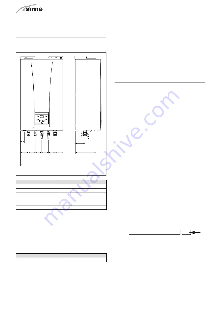
Plumbing connections

The plumbing connections have the following characteristics 

and dimensions.

135

101

65 65 65 65

=

=

48

420

M

Sc

Sc

U

G

E

R

Fig. 21

Description

MIA-30

M - System flow

Ø 22 mm

R - System return

Ø 22 mm

U - Domestic hot water output

Ø 15 mm

E - Domestic hot water inlet

Ø 15 mm

G - Gas cock connection

Ø 15 mm

Sc - Condensate outlet

Ø 21.5 mm

CAUTION

A sealed system must only be filled by a competent 

person (see section Method of filling a sealed sys-

tem page 34).

6.9.1  Plumbing accessories (optional)

To facilitate plumbing and gas connections to the systems, the 

accessories as shown in the table below are available and are 

to be ordered separately from the boiler.

DESCRIPTION

CODE

Installation plate

8075448

NOTE:

 kit instructions are supplied with the accessory itself or 

are to be found on the packaging.

6.10  Condensate outlet/collection

To ensure safe disposal of the condensate produced by the 

flue gases, reference should be made to BS6798:2009.

The boiler incorporates a condensate trap which has a seal of 

75 mm, therefore no additional trap is required.

The condensate trap can be filled prior to the installation of 

the flue by carefully pouring 1 litre of water into the exhaust 

connection.


NOTE: All pipework must have a continuous fall from the boil-

er and must be resistant to corrosion by condensate, copper 

or steel is NOT suitable. It should be noted that the connec-

tion of a condensate pipe to a drain may be subject to local 

building control requirements (Dealing with Condensate - see 

Appendix 1).

6.11  Gas supply

MIA-30

 boilers leave the factory prearranged for gas G20 and 

can also work with G31 without the need for any type of me-

chanical conversion. Simply select parameter

"03"

 (see “Pa-

rameter setting and display") page 37 and set the type of gas 

to be used.

If changing the type of gas to be used, carry out the entire 

appliance 

"COMMISSIONING"

 phase (page 36).

The gas connection must be made using seamless steel or 

copper tube.

Where the piping has to pass through walls, a suitable insulat-

ing sleeve must be provided.

When sizing gas piping, from the meter to the boiler, take into 

account both the volume flow rates (consumption) in m3/h 

and the relative density of the gas in question.

The sections of the piping making up the system must be such 

as to guarantee a supply of gas sufficient to cover the maxi-

mum output available from the boiler, limiting pressure loss 

between the gas meter and any apparatus being used to not 

greater than 1.0 mbar for family II gases (natural gas).

An adhesive data badge is sited inside the front panel; it con-

tains all the technical data identifying the boiler and the type 

of gas for which the boiler is arranged.

WARNING

Once installation has been completed, check that 

the joints are air tight as indicated in the installation 

Standards.

CAUTION

It is recommended that the gas line has a suitable 

filter.

CAUTION

If the gas supply is changed from G20 to G31, mark 

the box on the TECHNICAL DATA PLATE.

X

G31 - 37 mbar

Содержание MIA-30

Страница 1: ...838 INSTALLATION AND SERVICING INSTRUCTIONS ENSURE THAT THESE INSTRUCTIONS ARE LEFT FOR THE USER AFTER COMPLETION OF THE BENCHMARK SECTION PLEASE READ THE IMPORTANT NOTICE WITHIN THIS GUIDE REGARDING...

Страница 2: ...into its installation location Manoeuvring the boiler may include the use of a sack truck and involve lifting pushing and pulling Caution should be exercised during these operations Operatives should...

Страница 3: ...3...

Страница 4: ...ssioning instructions for filling in the checklist at the back of this installation guide Note All Gas Safe registered installers carry a ID Card You can check your installer is Gas Safe Registered by...

Страница 5: ...ign Directive 2009 125 EC Regulation UE N 811 2013 813 2013 Energy labelling Regulation EU No 2017 1369 SYMBOLS a WARNING To indicate actions which if not carried out correctly can result in injury of...

Страница 6: ...on guide If the power cable is damaged replace it with a cable ordered as a spare part with the same characteristics type X Assembly must be by carried out by a qualified professional m WARNINGS It is...

Страница 7: ...he safety or adjustment devices without authorization and in structions from the manufacturer d DO NOT To block the condensate drain To pull detach or twist the electrical cables coming out of the app...

Страница 8: ...8...

Страница 9: ...S SAFE REGISTERED BY CALLING ON 0800 408 5500 OR ALTERNATIVELY WWW GASSAFEREGISTER CO UK 1 USING THE BOILER MIA 30 10 1 1 Control panel 10 1 2 Preliminary checks 11 1 3 Ignition 11 1 4 Adjusting the d...

Страница 10: ...he boiler is op erating in Summer mode or if only the domestic hot water mode is enabled via the remote control If the symbols l and n are flashing this indicates that the chimney sweep function is ac...

Страница 11: ...set the main system switch to ON ON Fig 3 on the display check that the operating mode on the dis play is SUMMER land if necessary select it by pressing and holding the button s for at least 1 second...

Страница 12: ...ibed here contact a qualified technical professional 2 SHUTDOWN 2 1 Temporary shutdown To temporarily interupt the boiler operation press and hold the button s for at least one second once if in WINTE...

Страница 13: ...t on pro tective gloves 3 2 1 Cleaning the case When cleaning the cladding use a cloth dampened with soap and water or alcohol for stubborn marks d DO NOT Do not use abrasive products 4 DISPOSAL 4 1 D...

Страница 14: ...14...

Страница 15: ...E APPLIANCE 16 5 1 Characteristics 16 5 2 Check and safety devices 16 5 3 Identification 16 5 4 Structure 17 5 5 Technical features 18 5 6 Main water circuit 19 5 7 Sensors 20 5 8 Expansion vessel 20...

Страница 16: ...te the appliance with safety devices which do not work or which have been tampered with a WARNING Safety device may only be replaced by professional qualified personnel using Sime Ltd original spare p...

Страница 17: ...trol panel 10 Domestic hot water heat exchanger 11 Gas valve 12 Pressure gauge 13 Flow meter 14 System relief valve 15 Boiler drain 16 Pump 17 Water pressure switch 18 Automatic bleed valve 19 Fan 20...

Страница 18: ...Minimum heat input kW 4 8 D H W flow rate T 30 C l min 14 2 Continuous D H W flow rate T 25 C T 35 C l min 17 5 12 5 Minimum D H W flow rate l min 2 Max Min Pressure bar 7 0 5 kPa 700 50 ENERGY PERFO...

Страница 19: ...4 13 15 16 18 19 10 9 7 11 17 20 12 6 M U G E R Sc S 8 2 1 21 22 23 24 Fig 12 KEY M System flow R System return U Domestic hot water outlet E Domesti hot water inlet S Safety valve outlet G Gas supply...

Страница 20: ...cs Description U M MIA 30 Total capacity l 7 0 Prefilling pressure kPa 100 bar 1 0 Useful capacity l 4 45 Maximum system content l 110 Conditions of Average operating temperature 70 C with high temper...

Страница 21: ...op erating in Summer mode or if only the domestic hot water mode is enabled via the remote control If the symbols l and n are flashing this indicates that the chimney sweep function is active n WINTE...

Страница 22: ...SY HOME or HOME or HOME PLUS remote control alternative to TA1 To connect the TA remove the jumper between terminals 5 6 Fig 15 m CAUTION Installer must Connect the boiler to a 230v 50Hz single phase...

Страница 23: ...23...

Страница 24: ...tions by competent persons and that it meets the require ments of the appropriate Building Regulations The Benchmark Checklist can be used to demonstrate compliance with Building Regulations and shoul...

Страница 25: ...ional 28 6 10 Condensate outlet collection 28 6 11 Gas supply 28 6 12 Connecting the flue 29 6 12 1 Flue Terminal Positions 29 6 12 2 Installation of coaxial flues 60 100mm 80 125mm 30 6 12 3 Installa...

Страница 26: ...the appliance is to be handled manually tilting it slightly lifting it and applying pres sure in the points indicated in the figure Fig 18 d DO NOT To grip the appliance casing Hold the solid parts o...

Страница 27: ...amage to pump and valves boiler noise and circulation problems Before connecting the boiler the associated central heating system must be flushed in accordance with the guidelines given in BS 7593 Tre...

Страница 28: ...eel is NOT suitable It should be noted that the connec tion of a condensate pipe to a drain may be subject to local building control requirements Dealing with Condensate see Appendix 1 6 11 Gas supply...

Страница 29: ...e a nuisance should be avoided 75 mm 200 mm 75 mm 300 mm 1 200 mm 600 mm 300 mm 600 mm 1 200 mm 300 mm 3 in 8 in 3 in 12 in 48 in 24 in 300 mm 12 in 12 in 24 in 48 in 300 mm 12 in 1 500 mm 300 mm 300...

Страница 30: ...lled a diameter of 80 125 code 8095970 reduces the available length by 1 0 metres HORIZONTAL FLUES MUST BE LEVEL NOTE Before connecting accessories it is always advisable to lubricate the internal par...

Страница 31: ...let exhaust fitting code 8091401 10 Articulated tile code 8091300 11 Vertical roof terminal code 8091204 13 Inlet exhaust fitting code 8091401 14 Coaxial Terminal code 8091204 1 10 This loss includes...

Страница 32: ...thermostat timer or a dedicated control listed below For connection de tails see section External timers and Room Thermostats DESCRIPTION CODE External sensor kit 3435 NTC 10KOhm at 25 C 8094101 Power...

Страница 33: ...er the mains power is disconnected by setting the main system switch to OFF Sime Ltd declines all responsible for any injury or damage to persons animals or property as a result of failure to provide...

Страница 34: ...nsor and room ther mostat R M SE TA CR Fig 32 MULTI ZONE system with zone valve room thermostat and external sensor TA TZ1 VZ1 VZ2 VZ3 TZ2 TZ3 SE R M Fig 33 m CAUTION Set the parameter tS 1 7 DELAY SY...

Страница 35: ...the primary heat exchanger 3 8 5 4 9 Fig 38 NOTE to completely remove all air from the system it is rec ommended that this operation is repeated a number of times check the pressure on the pressure g...

Страница 36: ...r press and hold down the buttons o and at the same time for approximately 12 seconds until the flashing symbols l and n appear on the display as soon as the symbols begin to flash release the button...

Страница 37: ...splayed 7 4 List of parameters Type No Description Range U M Step Default CONFIGURATION tS 0 1 Index showing boiler power in kW 1 30 kW 1 tS 0 2 Hydraulic configuration 0 combi 1 system 2 N A 3 N A 4...

Страница 38: ...dulation AU Automatic 30 100 10 AU tS 4 1 T Modulating pump delivery Return 10 40 C 1 20 tS 4 2 Select heat pump or boiler convenience only if tS 0 2 6 20 30 C 5 tS 4 3 Heat pump boiler aid activation...

Страница 39: ...SPLAYED Type No Description Range U M Step CO 0 0 total no of boiler operating hours 0 99 h x 1000 0 1 from 0 0 to 9 9 1 from 10 to 99 CO 0 1 total no of burner operating hours 0 99 h x 1000 0 1 from...

Страница 40: ...l position and refit the front panel 2 Now con duct a flue gas analysis as detailed in APPENDIX 2 take a reading of the combustion data and measure the combustion efficiency press the button to make t...

Страница 41: ...shown in Parameter setting and display page 37 and adjust the parameter 15 tS 1 5 to that value Example Heating system with 8 radiators average 1 5 kW per radia tor total heat Requirement 12 kW 8 x 1...

Страница 42: ...regulations Make sure that the system components and pipes are not hot risk of burning a WARNING Before carrying out any interventions described isolate the power supply isolate the gas cock avoid co...

Страница 43: ...ombustion chamber The combustion chamber and the burner do not require any particular maintenance Simply brush them with a soft brush 8 3 3 Checking the ignition detection electrode Check the state of...

Страница 44: ...G20 1 G31 0 or 1 To enter Parameter setting and display refer to the indica tions provided in the specific section Once the parameters in the table have been set you must car ry out the entire phase...

Страница 45: ...k delivery sensor operation and position AL 74 Second delivery sensor fault Check second delivery sensor operation and position AL 77 EV2 SGV current max min absolute limits error Check gas valve and...

Страница 46: ...no what is the maximum central heating output selected kW Dynamic gas inlet pressure mbar C Central heating return temperature C System correctly balanced rebalanced Yes COMBINATION BOILERS ONLY Is t...

Страница 47: ...eer name Company name Telephone No Gas Safe registration No Max rate CO ppm CO CO CO Min rate CO ppm CO CO CO undertaken in accordance with manufacturers instructions and readings are correct yes Gas...

Страница 48: ...48 9 EXPLODED VIEWS Frame...

Страница 49: ...49 Hydraulic assembly...

Страница 50: ...50 Exchanger Combustion...

Страница 51: ...51 Control panel...

Страница 52: ...52 Additional components...

Страница 53: ...53...

Страница 54: ...ing cli 051 6281674 Group air intake C 052 6281667 Front panel insulators A Pos Code Description Advised parts 053 2030249 Gasket 24x17x3 054 6319653 External by pass kit C 055 6265866 C H flow manifo...

Страница 55: ...ork must be a minimum of 19mm ID typically 22mm OD plastic pipe or as per manufacturer s instructions and this should fall a minimum of 45mm per metre away from the boiler taking the shortest practica...

Страница 56: ...ir break is required Key 1 Boiler 2 Visible air break 3 75 mm trap 4 Visible air break and trap not required if there is a trap with a minimum condensate seal of 75 mm incorporated into the boiler 5 S...

Страница 57: ...nimum condensate seal of 75 mm incorporated into the boiler In this case the 100 mm is measured to the trap in the boiler 5 Sink basin bath or shower 6 Open end of condensate discharge pipe direct int...

Страница 58: ...er level end cut at 45 Note the maximum external condensate discharge length is 3 metres 6 Minimum internal diameter 19 mm 7 Pipe size transition 8 Minimum internal diameter 30 mm 9 Water weather proo...

Страница 59: ...used External waste pipes from kitchens utility rooms or bathrooms such as sink basin and bath or shower waste outlets should be insulated with waterproof UV resistant class 0 material terminated bel...

Страница 60: ...4 5 75mm sink waste trap 2 5 4 3 Key 1 Boiler 2 Visible air break at plug hole 3 75 mm sink basin bath or shower waste trap 4 Sink basin bath or shower with 5 Open end of condensate discharge pipe di...

Страница 61: ...ons should be followed The condensate pipe should be run internally as far as possible before going externally and the pipe diameter should be increased to a minimum of 30mm ID typically 32mm OD befor...

Страница 62: ...of 75mm incorporated into the boiler 5 Soil and vent stack 6 Invert 7 450mm minimum upto three storeys 8 Minimum internal diameter 19 mm 9 Pipe size transition point 10 Minimum internal diameter 30mm...

Страница 63: ...ub zero temperatures i e 15 C for 48 hours BS6798 refers to devices that gas BS6798 section 6 3 8 note 4 The boiler manufacturer s instructions will disposal of the condensate Additional Measures meas...

Страница 64: ...wed Insulation Materials Insulation used for external condensate pipes sink or washing machine waste pipes should be of class O grade with an outer coating that is weather proof is recommended for 32m...

Страница 65: ...ate discharge pipe from boiler 2 Pipe size transition point 3 Water weather proof insulation 4 43mm 90 male female bend 5 External rain water pipe into foul water 6 External air break 7 Air gap 8 9 Mi...

Страница 66: ...14 or boiler installation manual for soakaway design requirements any above ground section of condensate discharge pipe should be run and insulated as described above Figure 7 following page shows a s...

Страница 67: ...incorporated into the boiler refer to manufacturers instructions 5 External length of pipe 3 m maximum 6 Open end of condensate discharge pipe direct into gully 25 mm min below grating but above water...

Страница 68: ...be run either above or below round level End cut at 45 3 Diameter 100 mm minimum plastic tube 4 Bottom of tube sealed 5 Limestone chippings 6 Two rows of three 12 mm holes at 25 mm centres 50 mm from...

Страница 69: ...onnected to the boiler Is O2 less than or equal to 20 6 and CO2 less than 0 2 VERIFY FLUE INTEGRITY Analyser readings indicate that combustion products and inlet air must be mixing Further investigati...

Страница 70: ...l combustible consumption GJ 17 C H seasonal energy efficiency 93 D HW energy efficiency 86 Sound power dB A 57 Specific precautionary measures to be adopted at the time of assembly installation or ma...

Страница 71: ...perature regime b P1 7 8 kW At 30 of nominal heat output and low temperature regime 1 97 7 Auxiliary electricity consumption Other items At full load elmax 0 043 kW Standby heat loss Pstby 0 082 kW At...

Страница 72: ...Sime Ltd 1a Blue Ridge Park Thunderhead Ridge Glasshoughton Castleford WF10 4UA Phone 0345 901 1114 Fax 0345 901 1115 www sime co uk Email enquiries sime co uk...

Отзывы: