08.96
Options
Siemens AG 6SE7087-6BM70
6-11
SIMOVERT MASTER DRIVES Operating Instructions
6.6.1.3
Connecting and disconnecting individual converters to the DC bus
Sequence control
Switch the converter to the DC bus
Isolate the converter from the DC bus
Close the fuse disconnect switch
Output an off command
DC link is pre-charged through the pre-charging
resistors
Bypass contactor drops out
Enter an on command
Open the fuse disconnect switch
Bypass contactor is closed
Converter is electrically isolated from the DC bus
Wait until the DC link capacitors have completely
discharged
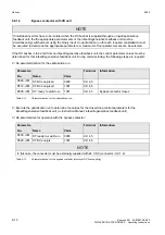
Table 6.14
Sequence control for connecting/disconnecting individual converters to the bus
6.6.2
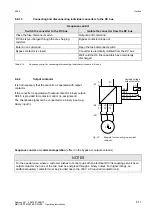
Output contactor
It is not necessary that the converter is operated with output
contactor.
If the converter is operated with output contactor, binary output-
X9:4,5 is provided for contactor control (re-assignment).
The checkback signal can be connected to a binary input (e.g.
binary input 3).
Sequence control, on command-operation (effect on the bypass-or output contactor)
NOTES
For the special case, where a customer wishes to connect-up both an electrical DC link coupling as well as an
output contactor, then one of the two must be energized through a binary output. For higher ratings, an
additional auxiliary contactor must be provided due to the 230 V AC required (contactor coil).
-X1
C/
L+
D/
L-
U2/
T1
V2/
T2
W2/
T3
-X2
-X9:4
Auxiliary voltage
output contactor
-K11
-X9:5
-X101:13
-X101:18
-K11
-K11
M
3
Fig. 6.7
Example for connecting-up a output
contactor


