08.96
Options
Siemens AG 6SE7087-6BM70
6-5
SIMOVERT MASTER DRIVES Operating Instructions
6.5.1
Output reactor, dv/dt filter
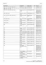
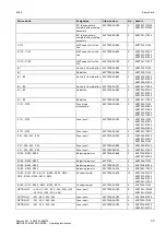
When longer feeder cables are used between the converter and motor:
♦
the converter has to cope with additional current peaks due to re-charging the cable capacitances
♦
the motor insulation is additionally stressed as a result of transient voltage spikes caused by reflection.
NOTE
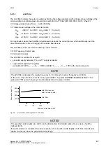
In order to prevent premature aging of the motor
insulation and thus early failures, the following limit
values may not be exceeded at the motor terminals:
♦
the permissible voltage gradient dv/dt and
♦
the permissible peak voltage between phase
conductors
)
V
LL
Fig. 6.3
Permissible limit values for the motor insulation
)
V
LL
1
2
3
4
500
1000
1460
1500
t [
µ
s]
for motors in accordance with IEC 34-17:1992
(DIN VDE 0530, Part1, Sheet2)
[V]
for Siemens 1LA2, 1LA5, 1LA6
and 1LA8*) motors
*)
Standard 1LA8 motors;
1LA8 motors with improvedinsulation are available
Depending on the application, the voltagerate-of-rise, voltage and current peaks can be reduced using the
following options: Output reactor, dv/dt filter.
Characteristics of the output reactors and dv/dt filters:
Output
reactor
dv/dt filter
Reduces the current peaks for long cables
yes
yes
Reduces the voltage gradient (rate of rise) dv/dt at the motor
terminals
slightly
yes
Limits the amplitude of the transient voltage peaks at the motor
terminals to the following typical values
≤
800 V at 3AC 400 V to 460 V
≤
1000 V at 3AC 500 V to 575 V
≤
1250 V at 3AC 660 V to 690 V
no
yes
Reduces the supplementary losses in the motor
no
no
Reduces motor noise (corresponding to direct online operation)
no
no
Table 6.8


