08.96
Options
Siemens AG 6SE7087-6BM70
6-7
SIMOVERT MASTER DRIVES Operating Instructions
6.5.1.2
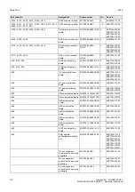
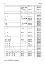
dv/dt filter
The dv/dt filter protects the motor insulation by limiting the voltage gradient and the transient peak voltage at the
motor winding to uncritical values in accordance with IEC 34-17:1992 (DIN VDE 0530, Part 1, Sheet 2):
♦
Voltage gradient (rate of rise)
dv/dt
≤
500 V/
µ
s
♦
Transient peak voltage at the motor terminals:
Û
typ.
≤
800 V for 380 V
≤
U
N
≤
460 V
(3 ph. AC)
Û
typ.
≤
1000 V
for 500 V
≤
U
N
≤
575 V
(3 ph. AC)
Û
typ.
≤
1250 V for 660 V
≤
U
N
≤
690 V
(3 ph. AC).
For long feeder cables, the dv/dt filter simultaneously reduces the current spikes, which additionally load the
drive converter due to the re-charging of the cable capacitances.
The dv/dt filter can be used for the following control versions
♦
FC (Frequency Control) and
♦
VC (Vector Control)
The dv/dt filter is suitable for use with
•
grounded supply networks (TN- and TT supply networks)
•
ungrounded supplies (IT supplies)
(exceptions: 6SE70_ _ - _ _ B _ _ -1FD0 and 6SE70 _ _ - _ _ C _ _ -1FD0 with version release A)
NOTE
The dv/dt filter is designed for a pulse frequency f
p
= 3 kHz and an output frequency f
A
≤
300 Hz.
In this case, when the drive converter is being set (P052 = 5), parameter P092 should be set to 2. Thus,
parameter P761 (pulse frequency) is automatically limited to values
≤
3 kHz.
dv/dt filter
1000
100
10
1
100
200
300
400
Ma
x
.
c
a
b
le
l
e
n
g
th
/ m
Drive converter output / kW
dv/dt filter in series
with the output reactor
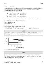
Fig. 6.5
Permissible cable lengths with dv/dt filter
NOTES
The specified cable lengths are valid for unshielded cables; for shielded cables, these values should be
reduced to 2/3.
If several motors are connected to a drive converter, the sum of the cable lengths of all of the motor feeder
cables must be less than the permissible cable length.


