Flexible automation concepts
10.2 Configuration control (option handling)
Automation system
System Manual, 12/2017, A5E03461182-AE
211
10.2.2.1
Control data record for the S7-1500 Automation System
Slot assignment
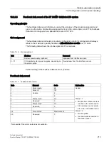
The following table shows the slot assignment of the modules for the S7-1500 automation
system:
Table 10- 2 Slot assignment
Slot
Modules
Comment
0
System power supply (optional)
Upstream of CPU
1
CPU
Slot 1 is always the CPU
2 - 31
I/O modules/system power supplies, depending on
the station option
Downstream of CPU
Control data record
For configuration control of the S7-1500 automation system, you define a control data record
196 V4.0, which contains a slot assignment. The table below shows the structure of a control
data record with explanations of the individual elements.
Table 10- 3 Configuration control: Structure of control data record 196
Byte
Element
Code
Explanation
0
Block length
4 + number of slots
Header
1
Block ID
196
2
Version
4
3
Version
0
4
Slot 0 of the station master Slot assignment in the
station option
Control element
Contains information on which module is
inserted in which slot.
The following rule determines which value
you must enter in the respective byte:
•
If the module is included in the station
option, enter the slot number of the
module.
•
If the module is not included in the
station option, enter 255.
5
Slot 1 of the station master Slot assignment 1 in the
station option
(always 1, because the
CPU is always in slot 1)
6
Slot 2 of the station master Slot assignment in the
station option
7
Slot 3 of the station master Slot assignment in the
station option
:
:
:
4 + (max. slot num-
ber)
Maximum slot of the station
master
Slot assignment in the
station option
Содержание Simatic S7-1500/ET 200MP
Страница 1: ......


