Configuring
7.1 Configuring the CPU
Automation system
System Manual, 12/2017, A5E03461182-AE
171
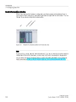
Example for the assignment of channel addresses (analog module)
The following figure shows how the addresses of the individual channels of the analog input
module (e.g., 6ES7531-7NF10-0AB0) are determined when the module has the start
address 256.
Figure 7-9
Example for the assignment of channel addresses (analog module)
Note
You can assign symbolic names to the addresses at the following locations in STEP 7:
•
PLC tag table
•
Properties of the module in the "IO Tags" tab.
Содержание Simatic S7-1500/ET 200MP
Страница 1: ......

