background image

xx

 ET 200U Distributed I/O Station

 EWA 4NEB 812 6087–02b

8-1

Binary representation of the measured value

8-58

. . . . . . . . . . . . . . . . . . . . . . . . 

9-1

Sending Data from the Counter Modules to the CPU

9-26

. . . . . . . . . . . . . . . . . . 

9-2

Sending Data from the CPU to the Counter Module

9-26

. . . . . . . . . . . . . . . . . . . 

9-3

Pulse Evaluation

9-31

. . . . . . . . . . . . . . . . . . . . . . . . . . . . . . . . . . . . . . . . . . . . . . . . . 

9-4

Sample Traverse Range

9-32

. . . . . . . . . . . . . . . . . . . . . . . . . . . . . . . . . . . . . . . . . . 

9-5

Reaction of the Counter Module during Transfer of the Setpoints

9-40

. . . . . . . 

9-6

Meaning of the Bytes of a Slot Address

9-42

. . . . . . . . . . . . . . . . . . . . . . . . . . . . . 

9-7

Designation of the Operating Modes of the IP 266

9-62

. . . . . . . . . . . . . . . . . . . . 

Contents

Содержание SIMATIC S5 ET 200U

Страница 1: ...al Configuration ET 200U DP Siemens Address Assignment Starting Up Diagnosing Faults EWA 4NEB 812 6087 02b ET 200U DP Standard Address Assignment Starting Up Diagnosing Faults Analog Value Processing Module Spectrum Function Modules Safety Related Guidelines Glossary ET 200U DP Standard FMS Modes Settings and Comm Cap of the IM 318 C ...

Страница 2: ...description of the safety related guidelines please refer to the Appen dix Please observe the following Warning The equipment system or the system components may only be used for the applica tions described in the catalog or the technical description and only in combination with the equipment components and devices of other manufacturers as far as this is recommended or permitted by Siemens The pr...

Страница 3: ... the PROFIBUS solution for high speed field applications FMS is the PROFIBUS bus protocol described in DIN 19245 Part 2 This manual is based on the ET 200 Distributed I O System Manual The manual is structured as follows Which control and display elements does the ET 200U have How is the ET 200U installed How is the ET 200U DP Siemens started up with COM ET 200 How is the ET 200U DP Standard start...

Страница 4: ...el 1 The functionality of the 318 8MB11 module is a subset of the functions of the 318 8MB12 Additionally the 318 8MB12 operates in accordance with the PROFIBUS DP DIN 19245 Part 3 draft standard in the following referred to as DP Standard The draft standard will be explained in detail in Section 1 3 Note A 318 8MB12 module can be operated as DP Standard slave ET 200U DP Standard in conjunction wi...

Страница 5: ... interface modules Difference Described in Pulling and plugging in of I O modules under load voltage is only permitted under defined conditions Chapter 3 Depending on whether the DP Siemens or the DP Standard proto col is used COM ET 200 requires different address identifiers for the modules Table 4 1 Section 4 1 1 and Table 5 1 Section 5 1 1 Different functions of switch 8 SLOW mode Section 4 2 1...

Страница 6: ...n the following Important information is marked specifically Warning You will find the definitions for the terms Danger Warning and Cau tion in the Safety Related Guidelines on the page following the front page Footnotes are marked with a raised number e g 1 or a raised asterisk You will find the corresponding explanations in the lower margin of the page Enumerations are marked with a black point ...

Страница 7: ... One Tier 3 3 Installing PS 931 Power Supply Module 3 4 Installing PS 935 Power Supply Module 3 4 Installing Bus Units 3 5 Installing an I O Module on a Bus Unit 3 6 Dismantling 3 7 Expanding an ET 200U Slave Station to Several Tiers 3 9 Addressing with Multi Tier Configuration 3 11 3 2 Wiring the ET 200U Distributed I O Station 3 12 Wiring Methods 3 12 Screw Type Connections 3 12 Crimp Snap In Co...

Страница 8: ...nts for Operation 4 2 4 1 Assigning Addresses Using COM ET 200 4 3 In this Section 4 3 4 1 1 Using the CONFIGURING Screen for ET 200U DP Siemens 4 4 Station Number 4 5 Area 4 6 Station Type 4 6 Next Available Address 4 7 Special Address Assignment Conditions 4 7 Condition 1 4 8 Condition 2 4 8 Example Division of the Digital Analog I O Areas 4 8 Configuring 4 9 DP Siemens Address ID 4 9 Finish Con...

Страница 9: ...Diagnostics 4 34 Request Module Diagnostics 4 35 Read Module Diagnostics 4 35 5 ET 200U DP Standard Address Assignment Starting UP and Diagnosing Faults Using COM ET 200 5 1 Prerequisites for this Chapter 5 1 In this Chapter 5 1 For Reference 5 1 What is DP Standard 5 2 Requirements for Operation 5 2 5 1 Assigning Addresses Using COM ET 200 5 3 In this Section 5 3 Copying the Type File 5 3 5 1 1 U...

Страница 10: ...ms 5 30 5 3 3 Diagnosing Faults with STEP 5 Station Diagnostics 5 32 General Remarks on Diagnostics 5 32 Special Features of Requesting Diagnostics Using Page Addressing 5 32 Structure and Request of Station Diagnostics for ET 200U 5 33 Request Station Status 5 34 Read Station Status 5 34 Request Manufacturer Identification 5 36 Request Station Diagnostics 5 37 Read Station Diagnostics 5 37 Reques...

Страница 11: ... 6 33 RSAP 6 33 RADR 6 33 SCC 6 33 RCC 6 33 SAC 6 33 RAC 6 33 ACI CCI 6 34 Max PDU Size 6 34 Features Supported 6 34 6 4 Using LEDs to Diagnose Problems 6 35 6 5 Example of Programming a Link between an ET 200U FMS and a CP 5431 FMS 6 36 6 5 1 Programming a Cyclic Link MSZY 6 37 6 5 2 Programming an Acyclic Link MSAZ 6 39 7 Analog Value Processing 7 1 7 1 Analog Input Modules 7 2 7 2 Connecting Cu...

Страница 12: ... 8 2 8 2 IM 318 B Interface Module 6ES5 318 8MB11 6ES5 318 8MB12 6ES5 318 8MC11 8 3 8 3 Power Supply Modules 8 7 8 4 Bus Units 8 12 8 5 Interface Modules 8 14 8 6 Digital Input Modules 8 16 8 7 Digital Output Modules 8 26 8 8 Digital Input Output Modules 8 39 8 9 Analog Input Modules 8 41 8 10 Analog Output Modules 8 59 9 Function Modules 9 1 9 1 Comparator Module 2 x 0 5 to 20 mA 0 5 to 10 V 6ES5...

Страница 13: ...ing 9 42 9 7 Closed Loop Control Module IP 262 6ES5 262 8MA12 6ES5 262 8MB12 9 44 Function 9 46 Modules 9 46 Installation 9 46 Addressing 9 47 Operating Modes 9 47 9 8 IP 263 Positioning Module 6ES5 263 8MA11 9 48 Assignments of Outputs 9 50 Positioning 9 50 9 9 IP 264 Electronic Cam Controller Module 6ES5 264 8MA11 9 52 Dead Time Compensation 9 54 Direct Process Connection 9 54 9 10 IP 265 High S...

Страница 14: ...sor 6ES5 521 8MA21 9 68 Function 9 69 Unidirectional Data Exchange 9 69 Bidirectional Data Exchange 9 69 Integrated Real Time Clock 9 70 Installation 9 70 Addressing 9 70 A Safety Related Guidelines A 1 A 1 Active and Passive Faults in Automation Equipment A 2 Procedures for Maintenance and Repair A 2 A 2 Suggestions for Configuring and Installing a Programmable Controller A 3 B Glossary B 1 Conte...

Страница 15: ...dule Sensors and Actuators Safe Electrical Isolation According to VDE 0160 3 26 3 20 Ungrounded Configuration with a 24 V DC Power Supply for an ET 200U Interface Module 3 27 3 21 Simplified Illustration of a Configuration with Nonfloating I O Modules 3 29 3 22 Simplified Illustration of a Configuration with Floating I O Modules 3 31 4 1 ET 200U DP Siemens CONFIGURING Screen 1 4 4 4 2 ET 200U DP S...

Страница 16: ... of Module Diagnostics Header and Slots 0 to 7 5 38 5 17 Structure of the Diagnostics Word after Request of Module Diagnostics Slots 8 to 15 and 16 to 23 5 39 5 18 Structure of the Diagnostics Word after Request of Module Diagnostics Slots 24 to 31 5 39 6 1 Location of the Bank of Switches for Setting the Station Number 6 9 6 2 FMS Services Supported by the ET 200U DP Standard FMS 6 11 6 3 Fault L...

Страница 17: ...ng 9 24 9 14 Assignment Diagram for the Terminal Block 9 25 9 15 Diagnostics Byte 9 27 9 16 Switching the Outputs Dependent on the Status of the Counter and the Enable Input 9 30 9 17 Position of the Reference Point SYNC Bit 0 1 within the Reference Signal Range 9 34 9 18 Position of the Reference Point SYNC Bit 1 after the Reference Signal 9 34 9 19 Position of the Reference Point SYNC Bit 1 duri...

Страница 18: ...ned On 5 27 5 10 LED Fault Messages on ET 200U Interface Module 5 29 5 11 Diagnostics with STEP 5 5 32 5 12 Structure of Station Diagnostics and Module Diagnostics 5 33 6 1 Modes of the M 318 C 6 4 6 2 Requirements for Operating an IM 318 C 6 5 6 3 Bus Parameters to be Set if at Least One FMS Master is on the Bus 6 5 6 4 Differences between the Various Modes of the IM 318 C 6 6 6 5 Setting the Sta...

Страница 19: ...F11 8MB11 Bipolar Fixed Point Number 7 17 7 6 Analog Input Modules 464 8MC11 8MD11 Bipolar Fixed Point Number 7 18 7 7 Analog Input Module 464 8ME11 4 4 to 20 mA Absolute Value 7 18 7 8 Analog Input Module 464 8MF11 2 PT 100 Unipolar Analog Input Module 464 8MF21 2 PT 100 No Linearization Unipolar 7 19 7 9 Analog Input Module 464 8MF21 2 PT 100 with Linearization Bipolar to DIN IEC 751 7 19 7 10 A...

Страница 20: ...e Counter Modules to the CPU 9 26 9 2 Sending Data from the CPU to the Counter Module 9 26 9 3 Pulse Evaluation 9 31 9 4 Sample Traverse Range 9 32 9 5 Reaction of the Counter Module during Transfer of the Setpoints 9 40 9 6 Meaning of the Bytes of a Slot Address 9 42 9 7 Designation of the Operating Modes of the IP 266 9 62 Contents ...
Страница 21: ... ET 200 1 2 1 2 What is ET 200U 1 3 Components 1 3 Characteristics 1 3 1 3 What is DP Siemens and DP Standard 1 4 What is DP Siemens and DP Standard 1 4 Differences between DP Siemens and DP Standard 1 4 What Does DIN 19245 Have to Offer 1 4 What is FMS 1 5 Definition 1 5 Figures 1 1 Component of the ET 200 Distributed I O System Described in this Manual 1 2 1 ...

Страница 22: ...m Overview The system overview contains information on the performance characteristics and features of the ET 200U distributed I O station It also contains information on the ET 200U distributed I O station seen as a component of the ET 200 distributed I O system 1 ...

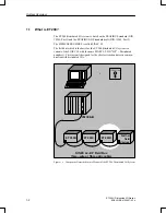
Страница 23: ... The field bus which is the basis for the ET 200 distributed I O system is a variant of the SINEC L2 with the name SINEC L2 DP DP Distributed periphery This variant is designed for the shortest reaction times in commu nication with distributed I Os IM 308 B SINEC L2 DP Field Bus Two wire or fibre optic cable ET 200C ET 200B ET 200U Further field devices Figure 1 1 Component Described in this Manua...

Страница 24: ...ion of a programmer or ET 200 Handheld for testing and start up programmer with a CP 5410 S5DOS ST programmer interface module The station number of the ET 200U distributed I O is switch selectable The ET 200U module Order No 8MB11 is operated with DP Siemens Section 1 3 The ET 200U module Order No 8MB12 can be operated either with DP Siemens or with DP Standard Section 1 3 ET 200U module Order No...

Страница 25: ...e with the ET 200U DP Standard slave station The PROFIBUS DIN 19245 field bus standards cover a great variety of func tions thus making the bus system suitable for universal use from the control and cell level right up to the field level The ET 200 distributed I O system is based on DIN 19245 Part 1 and supple ments the definitions contained therein for the special applications in the field of dis...

Страница 26: ...ion systems The DP protocol offers faster response times than FMS so that FMS is inten ded rather for applications where time is not a crucial factor In this manual the following three terms are used to distinguish the different systems ET 200U Slave station with IM 318 B interface module in gene ral ET 200U DP Siemens 318 8MB11 or 318 8MB12 which uses the DP Siemens bus proto col just like a 318 ...

Страница 27: ... I O Station EWA 4NEB 812 6087 02b Technical Description 2 1 Design of the ET 200U Interface Module 2 2 2 2 Technical Specifications 2 4 Spectrum of I O Modules 2 4 Figures 2 1 Design of the ET 200U Interface Module 2 3 2 ...

Страница 28: ...NEB 812 6087 02b Technical Description The ET 200U distributed I O station consists of the ET 200U interface mo dule and the I O modules This chapter contains a description of the controls and display elements of the ET 200U interface module 2 ...

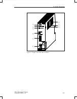
Страница 29: ... and functional earth Switch for setting the station number and S the baud rate of the I O bus 8MB11 Section 4 2 1 or S DP Siemens DP Standard characteristics 8MB12 Section 5 2 1 or S Switching from FMS to DP Standard bus parameters and vice versa 8MC11 Section 6 2 Field for station number labels Plug connector for connection of a bus unit The LED indications are described in detail in the followi...

Страница 30: ...2 3 ET 200U Distributed I O Station EWA 4NEB 812 6087 02b Figure 2 1 Design of the ET 200 Interface Module Technical Description ...

Страница 31: ... O modules which can be configured with COM ET 200 can be used for configuring the ET 200U distributed I O station For an overview of the I O modules which can be connected see Chapters 8 and 9 Exception If the ET 200U is operated as a combi slave no CPs or IPs are permitted in the ET 200U Section 6 Spectrum of I O Modules Technical Description ...

Страница 32: ...s 3 14 Connecting a PS 931 or PS 935 Power Supply Module to the Main Power 3 15 Connecting an ET 200U Interface Module to a PS 931 or PS 935 Power Supply Module 3 15 Connecting Digital Modules 3 16 Connecting Four Channel Digital Modules 3 16 Connecting Four Channel Input Modules 3 17 Connecting Four Channel Output Modules 3 18 Connecting Eight Channel Digital Modules 3 19 Connecting Eight Channel...

Страница 33: ... 3 18 3 15 Connecting a Sensor to Channel 4 3 19 3 16 Connecting a Lamp to Channel 6 3 20 3 17 Connecting a Sensor and Load to the 482 Digital I O Module 3 22 3 18 Configuration with a 115 V AC 230 V AC Power Supply for an ET 200U Interface Module Sensors and Actuators 3 25 3 19 Grounded Configuration with a 24 V DC Power Supply for an ET 200U Interface Module Sensors and Actuators Safe Electrical...

Страница 34: ...tion Installing a station electrically The degree to which you can expand a slave station is limited by the follow ing factors The number of modules you can connect a maximum of 16 bus units or 32 modules The addressing range of an ET 200U slave station a maximum of 32 input bytes and 32 output bytes The current consumption of the individual modules total current consumption from 9 V DC I O bus 70...

Страница 35: ...ng dismantling and replacing the hardware of an ET 200U station Table 3 1 Installing Dismantling and Replacing the Hardware of an ET 200 Sta tion Installing Dismantling and Replacing Prerequisites I O Modules Put the RUN STOP switch of the ET 200U interface module in the STOP position Turn off the load power supply of the I O module Bus Units Interface Mo dules Power Supply Mo dules Disconnect the...

Страница 36: ... voltage is available Begin your installation at the left end of the standard mounting rail Add modules from left to right This section discusses the following subjects Installing a power supply module and an ET 200U interface module Installing bus units Installing I O modules on bus units You will find notes on dismantling the ET 200U distributed I O station at the end of the assembly instruction...

Страница 37: ...odule Other than the PS 931 the PS 935 power supply module is located on the right hand side of the ET 200U interface module 1 Connect the ET 200U interface module and the PS 935 power supply mo dule via the ribbon cable of the PS 935 The ET 200U interface module is then located on the left hand side of the PS 935 2 Attach the ET 200U interface module together with the PS 935 onto the standard mou...

Страница 38: ... bus units to the right of the first bus unit using the same method Hooks on the sides of the bus units ensure a mechanical connection between the units 4 On the upper left of the bus unit is a ribbon cable Pull the connector of the ribbon cable out of its holder see Figure 3 2 5 Plug the connector of the ribbon cable into the male connector on the right side of the ET 200U interface module PS 935...

Страница 39: ... the front of the I O module Setting the coding key to the correct module type prevents installing the wrong type of module when you change modules 1 2 Hang the module on the top of the bus unit 2 3 Swing the module back 3 4 Press the module into place 5 Fasten the screw on the bottom front of the module to attach the module to the bus unit Figure 3 3 System to Prevent Plugging In the Wrong Module...

Страница 40: ...connect the ET 200U interface module from the power supply unit 3 Using a screwdriver press down on the slide on the bottom of each mo dule 4 Swing the module up and off of the standard mounting rail Figure 3 4 Removing an ET 200U Interface Module from a Rail Remove I O module 1 Loosen the screw at the bottom of the module and swinging the module up and out of the bus unit Dismantling Mechanical a...

Страница 41: ...ng bus unit or from the ET 200U interface module see 1 in Figure 3 5 3 Using a screwdriver press down on the bottom of the slide on each unit 2 3 4 Swing the bus unit or the ET 200U interface module up and off of the standard mounting rail 4 Figure 3 5 Removing Bus Units from a Standard Mounting Rail Mechanical and Electrical Configuration ...

Страница 42: ... to connect the two modules and secure the connectors of the cable with two screws each see Figure 3 6 Make sure that you include at least 210 mm 8 3 in net clearance between the tiers see Figures 3 6 and 3 7 Figure 3 6 shows a multi tier configuration using IM 316 interface modules in a cabinet Cabinet installation can be necessary under following conditions In danger of coming into contact with ...

Страница 43: ... Metal Plate IM 316 Interface Module In Socket Out Socket Connecting Cable 712 8 Minimum 210 mm 8 3 in Minimum210 mm 8 3 in PS IM 318 Figure 3 6 Multi Tier Configuration in a Cabinet Using IM 316 Interface Modules Row of Devices and or a Cable Duct a PS IM 318 Minimum 210 mm 8 3 in a Minimum 45 mm 1 8 in Figure 3 7 Multi Tier Configuration with a Row of Devices Mechanical and Electrical Configurat...

Страница 44: ... ET 200U is configured in more than one tier numbering of the expan sion tiers is continued with the slot at the far left end PS IM 318 0 1 2 3 4 5 6 7 8 9 10 11 12 13 14 15 Figure 3 8 Numbering with Multi tier Configuration When expanding the configuration it is essential that you always mount the additional bus units in the top tier on the right Otherwise the slot numbers of the bus units to the...

Страница 45: ... snap in Using this wiring method you can clamp two lines to each terminal point of a bus unit To screw them tight it is best to use a screw driver with a blade that is 5 mm approximately 3 16 in wide Figure 3 9 illustrates a screw type connection The following table lists the permissible cross sections of lines you can connect to this type of terminal Type of Conductor Permissible Cross Section S...

Страница 46: ...s follows see also Figure 3 10 1 Using a screw driver press the terminal block down 1 2 Turn the terminal block approximately 180 until the back of the module is visible 2 3 Push the contact into the desired recess until the locating spring engages The locating spring must point into the slot 3 4 Pull lightly on the line to ensure that the contact is properly engaged 5 Turn the terminal block back...

Страница 47: ...ed as follows 1 Put the extraction tool into the slot next to the contact so that you can compress the barb 1 2 Place the line in the groove of the extraction tool and pull the tool and line out 2 3 To use the contact again straighten out the deformed barb Figure 3 11Dismantling Crimp Snap In Contacts Dismantling Crimp Snap In Contacts Mechanical and Electrical Configuration ...

Страница 48: ... module to a power supply module is different for the PS 931 and PS 935 PS 931 PS 935 1 Connect the L and M terminals of the PS 931 power supply mo dule to the correspond terminals on the ET 200U interf module 1 Connect the L terminal of the PS 935 power supply module to the correspond terminals on the ET 200U interf module 2 For a grounded configuration connect the terminal of the ET 200U in terf...

Страница 49: ...r a two wire connection you can wire directly to a sensor or an actuator without using an external dis tribution block All 24 V DC four channel digital modules have a red F LED to indicate faults This LED signals a failure of the load voltage Where inputs are con cerned this LED also indicates a short circuit of M in the sensor lines Where outputs are concerned this LED indicates an output error T...

Страница 50: ...to a four channel input module Example A sensor is connected to an input module with start address 3 0 The sensor is connected to channel 2 address I 3 2 1 3 5 7 9 2 4 6 8 10 Channel 2 L M Sensor Figure 3 13 Two Wire Connection of a Sensor to Channel 2 Connecting Four Channel Input Mo dules Mechanical and Electrical Configuration ...

Страница 51: ...p to a four channel output module Example A lamp is connected to an output module with start address 1 0 The lamp is connected to channel 2 address Q 1 2 1 3 5 7 9 2 4 6 8 10 Channel 2 L M Lamp Figure 3 14 Two Wire Connection of a Lamp to Channel 2 Connecting Four Channel Output Modules Mechanical and Electrical Configuration ...

Страница 52: ...on diagram are printed on the front panel of the module When connecting eight channel input modules you must connect a sensor to terminal 1 via the L terminal strip A sensor is connected to an input module with start address 3 0 The sensor is connected to channel 4 address I 3 4 1 3 5 7 9 4 6 8 10 Channel 4 L M Sensor Channel 0 Channel 1 2 L Terminal Strip Figure 3 15 Connecting a Sensor to Channe...

Страница 53: ...ital output module Fig ure 3 15 illustrates the following example for connecting a lamp to an eight channel output module A lamp is connected to an eight channel output module with start address 5 0 The lamp is connected to channel 6 address Q 5 6 1 3 5 7 9 2 4 6 8 10 Channel 6 L M Lamp Channel 0 Channel 1 M Terminal Strip Figure 3 16 Connecting a Lamp to Channel 6 Connecting Eight Channel Output ...

Страница 54: ...ess 1 bit 1 0 5A 3 Module address 1 bit 1 4 Module address 1 bit 2 0 5A 4 Module address 1 bit 2 5 Module address 1 bit 3 0 5A 5 Module address 1 bit 3 6 Module address 1 bit 4 0 5A 6 Module address 1 bit 4 7 Module address 1 bit 5 0 5A 7 Module address 1 bit 5 8 Module address 1 bit 6 0 5A 8 Module address 1 bit 6 9 Module address 1 bit 7 0 5A 9 Module address 1 bit 7 10 M for connections 2 to 9 ...

Страница 55: ...o have different addresses A sensor is connected to input I 6 4 and a lamp is connected to output Q 7 3 See Figure 3 17 for the front connections 20 19 18 17 16 15 14 13 12 11 10 9 8 7 6 5 4 3 2 1 M L Sen sor IN OUT L M Lamp M Terminal L Terminal 20 19 18 17 16 15 14 13 12 11 10 9 8 7 6 5 4 3 2 1 Figure 3 17 Connecting a Sensor and Load to the 482 Digital I O Module Example Mechanical and Electric...

Страница 56: ...e voltage must be in a range of 20 V to 30 V including ripple and the load power supply must be safely isolated to DIN VDE 0160 Note If you use switch mode power supply units to supply floating analog modu les and BERO poximity limit switches you must first run this supply through a line filter Figures 3 18 through 3 20 show the following configurations for an ET 200U slave station Configuration w...

Страница 57: ... DC load circuits You need a back up capacitor rating 200 F per 1 A load current for nonstabilized load power supply units If you have AC load circuits with more than five actuating coils galvanic isolation by means of a transformer 4 is recommended You should ground the load circuit at one end see Figure 3 19 Use a low resistance conductor to connect the standard mounting rail to the cabinet chas...

Страница 58: ... 2 5 4 DE DA DA DE ET 200U interf mod PS Terminal 1 Terminal 2 10 6 7 AC 230 V 3 9 11 M line not provided with PS 935 Figure 3 18 Configuration with a 115 V AC 230 V AC Power Supply for an ET 200U Interface Module Sensors and Actuators Mechanical and Electrical Configuration ...

Страница 59: ...nection 5 to the protective ground conductor see Figure 3 19 Ground all machine parts L1 L2 L3 N PE 1 2 5 DI DQ DQ DI ET 200U interf mod Terminal 1 Terminal 2 10 6 7 3 9 M L L M Figure 3 19 Grounded Configuration with a 24 V DC Power Supply for an ET 200U Interface Module Sensors and Actuators Safe Electrical Isolation According to VDE 0160 Grounded Confi guration Mechanical and Electrical Configu...

Страница 60: ...ective ground and the chassis ground of the power supply You must provide fault voltage monitoring for load circuits that are not grounded 8 L1 L2 L3 N PE 1 2 8 ET 200U interf mod 3 9 M L Load circuit U Figure 3 20 Ungrounded Configuration with a 24 V DC Power Supply for an ET 200U Interface Module Ungrounded Con figuration Mechanical and Electrical Configuration ...

Страница 61: ...oltage limitation see Figure 3 20 Do not connect the ground terminal of the ET 200U interface module to the grounded standard mounting rail For a grounded configuration connect the ground terminal of the Et 200U interface module to the grounded standard mounting rail see Figure 3 19 Note If the ET 200U interface module is earthed then the GND line of the I O bus is also grounded because ground con...

Страница 62: ...rminal block A voltage drop DV2 on line increases the chassis ground of the output driver and in this way lowers the resulting control voltage VST see Figure 3 21 For a nonfloating configuration make sure that the voltage drop on lines and never exceeds 1 V Otherwise the reference potentials shift and the modules can malfunction see Figure 3 21 ET 200U interf mod L 9 V VE VST M D V1 D V2 1 2 1 2 2...

Страница 63: ...monitoring to ground with voltage limitation see Figure 3 20 Do not connect the ground terminal of the IM 318 B interface module to the grounded standard mount ing rail For a grounded configuration connect the ground terminal of the ET 200U interface module to the grounded standard mounting rail When the load cir cuit is grounded the grounding of the ET 200U interface module removes the galvanic i...

Страница 64: ...ributed I O Station EWA 4NEB 812 6087 02b ET 200U interface module 1L M L M N L1 M 2L 9 V Data GND Figure 3 22 Simplified Illustration of a Configuration with Floating I O Modules Mechanical and Electrical Configuration ...

Страница 65: ...emens Address ID 4 9 Finish Configuration 4 14 4 1 2 How to Proceed if the Configuration is Modified at a Later Point 4 15 Expanding the Slave Station at a Later Point 4 15 Expanding an Already Configured Slave Station 4 15 Modifying an Already Configured Slave Station 4 16 4 2 Starting Up and Testing with COM ET 200 for ET 200U DP Siemens 4 17 In this Section 4 17 4 2 1 Setting the Station No and...

Страница 66: ...Features of Requesting Diagnostics Using Page Addressing 4 29 Structure and Request of Station Diagnostics for ET 200U 4 30 Request Station Status 4 31 Read Station Status 4 31 Request Manufacturer Identification 4 33 Request Station Diagnostics 4 34 Read Station Diagnostics 4 34 Request Module Diagnostics 4 35 Read Module Diagnostics 4 35 ET 200U DP Siemens Address Assignment Starting Up Diagnosi...

Страница 67: ...he Diagnostics Word after Request of the Manufacturer Identification 4 33 4 14 Structure of the Diagnostics Word after Request of Station Diagnostics 4 34 4 15 Structure of the Diagnostics Word after Request of Module Diagnostics Header and Slots 0 to 7 4 35 4 16 Structure of the Diagnostics Word after Request of Module Diagnostics Slots 8 to 15 and 16 to 23 4 36 4 17 Structure of the Diagnostics ...

Страница 68: ...pe of slave station This chapter deals with the procedures applicable for ET 200U DP Siemens using COM ET 200 This chapter describes how to use COM ET 200 and STEP 5 for an ET 200U DP Siemens module The following features are described Address assignment using the CONFIGURING screen Section 4 1 Starting up and testing using the START UP TEST screen Section 4 2 Diagnosing faults using the DIAGNOSTI...

Страница 69: ...al Commission DKE and it has been passed as National draft standard DIN 19245 Part 3 For details on ET 200U DP Standard please refer to Chapter 5 The ET 200U with the Order No 6ES5 318 8MB12 is able to use both proto cols To set the required bus protocol use switch 8 on the bank of switches The bank of switches is described in Section 4 2 1 An ET 200U DP Siemens can be started up using any version...

Страница 70: ... ET 200U DP Sie mens You will learn how to use the COM ET 200 CONFIGURING screen to con figure the ET 200U DP Siemens distributed I O station Section 4 1 1 deals with configuring the ET 200U DP Siemens Section 4 1 2 deals with special configuring requirements In this Section ET 200U DP Siemens AddressAssignment Starting Up Diagnosing Faults Using COMET200 ...

Страница 71: ...figuration data to storing it 1 Maketheappropriateentries in the ET 200 SYSTEM PARAMETERS screen ET 200 Distributed I O System Manual After you confirm the ET 200 system parameters with the F6 ENTER key 2 Press F8 to return to the FUNCTIONS screen 3 From the FUNCTIONS screen press F2 to go to the CONFIGURING screen Result The CONFIGURING screen appears ENTER HELP EXIT F2 F3 F4 F5 F6 F7 F8 F1 Stati...

Страница 72: ...t been assigned yet the message NO STA TIONS CONFIGURED is output 4 If necessary correct the station number that appears on the screen and press F6 ENTER to complete your entry Result If the station whose number you entered has already been config ured its configuration appears on the screen after you complete your entry If the station whose number you entered has not already been configured two a...

Страница 73: ...Q peripheral area Press F7 HELP to select the station type 5 If you want to configure an ET 200U DP Siemens select ET 200U 6 Press F6 ENTER to confirm your entries Result COM ET 200 accepts the entries and fills the screen Configu ration field STATION DELETE STATION NEW STATION ADDRESS ASSIGN ENTER HELP EXIT F2 F3 F4 F5 F6 F7 F8 F1 Station number 3 Program file selected TEST ET 200 SIMATIC S5 COM ...

Страница 74: ...ke the following steps Separate the areas for digital and analog modules so that addresses do not overlap Communications processors CPs and intelligent I O modules IPs count here as analog modules Determine the structure of your stations Additions and changes that you make later result in address assignments that can be confusing to read or otherwise unclear CPUs 941 942 943 and 944 of the S5 115U...

Страница 75: ...ess I O image word by word Therefore the CPUs do not read write address 0 in the process I O image of station 1 although station 1 is available The CPU stops with timeout if in COM ET 200 timeout yes After a transition from STOP to RUN the CPU switches again to RUN Station 2 and address 0 of station 1 are not entered in the process I O image Note To avoid the above conditions note the following wh...

Страница 76: ...on If you are using page addressing note the following With page addressing peripheral byte 255 is assigned for selecting the page You can use more than one alternatives to enter the address ID of an ET 200U DP Siemens station as decimal number or as module code e g 8DE or 1AE COM ET 200 automatically converts the module code into a decimal number or press F7 HELP to obtain a list of all available...

Страница 77: ...Digital 15 3 440 8MA21 048 1 1 Digital 15 4 8 441 8MA11 8DQ or 017 1 1 Digital 14 3 5 450 8MB11 048 1 1 Digital 15 5 450 8MD11 4DQ or 016 1 1 Digital 14 3 5 451 8MA11 8DQ or 017 1 1 Digital 24 4 451 8MD11 8DQ or 017 1 1 Digital 25 3 5 451 8MR11 8DQ or 017 1 1 Digital 30 1 6 451 8MR12 8DQ or 017 1 1 Digital 30 1 6 452 8MR11 4DQ or 016 1 1 Digital 14 2 453 8MA11 8DQ or 017 1 1 Digital 20 1 457 8EA12...

Страница 78: ...el Analog 320 0 7 to 3 2 channel 2 ch 2 channel 2AI or 013 4 Analog Outputs 6ES5 470 8MA11 2AQ or 021 4 0 1 Analog 3 1 470 8MA12 2AQ or 021 4 0 15 Analog 3 1 470 8MB11 2AQ or 021 4 0 1 Analog 3 8 470 8MB12 2AQ or 021 4 0 15 Analog 3 8 470 8MC11 2AQ or 021 4 0 1 Analog 3 8 470 8MC12 2AQ or 021 4 0 15 Analog 3 8 470 8MD11 2AQ or 021 4 0 1 Analog 3 1 470 8MD12 2AQ or 021 4 0 15 Analog 3 1 470 8MD21 2...

Страница 79: ...1 9 Comparator Module 461 8MA11 4DI or 008 1 5 Digital 35 0 3 PID Controller Modules 2 262 8MA11 8MA12 223 8 100 to 200 Analog 20 262 8MB11 8MB12 223 8 100 to 200 Analog 20 Position Control Modules 263 8MA111 223 000 8 Analog 120 4 266 8MA11 223 8 Analog 267 8MA11 093 4 Analog 150 The address scope is necessary for the inputs and the outputs i e if the address scope is 2 bytes 2 bytes are used for...

Страница 80: ...1 223 8 Analog 180 1 6 CP 521 SI 521 8MA21 223 8 Analog 140 1 2 330 8MA11 or no module plugged in 000 0 0 The address scope is necessary for the inputs and the outputs i e if the address scope is 2 bytes 2 bytes are used for the inputs and 2 bytes are used for the outputs Since COM ET200 assigns the addresses for these modules optionally inputs and outputs can have different start addresses 1 The ...

Страница 81: ...nsferred separately in one message frame i e consistently over an area of two bytes By pressing the function keys you can activate the following functions If you want to do the following Then press the following key Name of the function key Display the configuration of the next higher config ured station F1 STATION Display the configuration of the next lower config ured station F2 STATION Delete t...

Страница 82: ... in the missing module later you must reconfigure as follows 1 Replace the 000 ID with the original address ID 2 Press F6 ENTER to confirm the configuration You want to add some I O modules to a station that you have already config ured 1 In the CONFIGURING screen press F4 NEW STATION to select the number of the station that you want to expand COM ET 200 displays the configuration of the selected ...

Страница 83: ... old module with the address ID of the new module 3 Press F6 ENTER to confirm the configuration The new module has a module start address that is not consecutive in the or der of the addresses of the stations that you configured previously The start address reflects a jump in addressing The address space that the old module took up is released and could be used for a module with the same address I...

Страница 84: ...DP Siemens The following describes How the station number and switch 8 are set Section 4 2 1 How you connect the ET 200U to the programmer Section 4 2 2 and How you use the COM ET 200 START UP TEST screen Section 4 2 3 In this Section ET 200U DP Siemens AddressAssignment Starting Up Diagnosing Faults Using COMET200 ...

Страница 85: ...ches on the bank of switches has a different positional value Positional value 1 Positional value 2 Positional value 4 Positional value 8 Positional value 16 Positional value 32 Positional value 64 Table 4 5 When switch is pressed ON the positional value is switched on 1 2 3 4 5 6 7 8 When switch is ON Figure 4 5 Location of the Bank of Switches for Setting the Station Number Setting the Station N...

Страница 86: ... 8MB12 DP Norm DP Standard Bus protocol to Draft Standard PROFIBUS DP can be used as from COM ET 200 version 4 0 DP Siemens Bus protocol to DP Siemens The ET 200U automatically switches into the slow mode when it identifies an IP 265 Set station number 52 and DP Siemens Press switch position ON 4 Positional value 16 32 52 1 2 3 4 5 6 7 8 Setting Switch 8 Example ET 200U DP Siemens AddressAssignmen...

Страница 87: ... link to the connected station assigns pa rameters to the station and displays the SYSTEM START UP TEST MO DULE SELECTION screen if the configuration in the program file and the actual station configuration match If the two configurations do not match COM ET 200 reports an error in the message line In such a case you must go to the CONFIGURATION screen to correct the station configuration Caution ...

Страница 88: ...dules whose input data you want to evaluate or whose outputs you want to force Result The selected modules are marked with an asterisk Pressing F5 SELECT a second time cancels the selection SELECT ENTER EXIT F2 F3 F4 F5 F6 F7 F8 F1 Station number 4 Program file selected TEST ET 200 SIMATIC S5 COM ET 200 SYSTEM START UP TEST MODULE SELECTION Station type ET 200U Station name PRESS Configuration 0 1...

Страница 89: ...ted B TEST ET 200 SIMATIC S5 COM ET 200 SYSTEM START UP TEST STATUS CONTROL Station type ET 200U Station name PRESS Station diagnostics Station cannot be controlled by PLC Slot Type Inputs Diagnost 00 01 02 03 04 05 HELP EXIT F2 F3 F4 F5 F6 F7 F8 F1 KM KH KM KM KH 01000100 01011100 10E0 0032 0104 0014 0000 00001110 0004 0012 101B 1AA4 Outputs 027 4AX 4DI 4DQ 8DX 4AI Figure 4 7 SYSTEM START UP TEST...

Страница 90: ... displays the state of the inputs in the INPUTS field in KM for mat for digital modules or in KH format for analog modules Inputs for a 464 8MA21 module module ID 4AI analog module Channel 4 3 2 1 KH 0001 1E00 00A0 0250 In the OUTPUTS field you can change the state of individual outputs al ways shown as 0 when this screen appears COM ET 200 displays the state of the outputs in KM format for digita...

Страница 91: ...you call up the MODULE SELECTION screen When you reset the outputs in the MODULE SELECTION screen When you exit from the MODULE SELECTION screen with F8 EXIT IM 308 B from version 5 and E E PROM pro grammed as ver sion w 3 When you call up the MODULE SELECTION screen When you reset the outputs in the MODULE SELECTION screen When you exit from the MODULE SELECTION screen with F8 EXIT When you power...

Страница 92: ...ults Using LEDs to diagnose problems Section 4 3 1 Using COM ET 200 to diagnose problems Section 4 3 2 Diagnosing faults with STEP 5 Section 4 3 3 Diagnosing faults with COM ET 200 in a STEP 5 program is described in detail in the ET 200 Distributed I O System Manual In this Section ET 200U DP Siemens AddressAssignment Starting Up Diagnosing Faults Using COMET200 ...

Страница 93: ...t and the IM 318 B interface module was not ad dressed During system start up or power up IM 318 B not parameterized yet No connection between SINEC L2 DP bus and slave station IM FAULT Lit or flashing There is a fault in the I O bus e g a bus unit is defective BUS FAULT and IM FAULT Lit There is a hardware fault in the ET 200U interface module BUS FAULT and IM FAULT Flashing The configured statio...

Страница 94: ...ted Programmer connected to the bus Y in the ET 200 SYS TEM PARAMETERS screen 1 Press F6 DIAGNOSE in the FUNCTIONS screen to call up the DIAGNOSTICS OVERVIEW screen Result The DIAGNOSTICS OVERVIEW screen appears Channel diagnost EXIT F2 F3 F4 F5 F6 F7 F8 F1 Station number 1 Program file selected C TEST ET 200 SIMATIC S5 COM ET 200 DIAGNOSTICS OVERVIEW Station type DP Master V x y System name Test ...

Страница 95: ...ss F6 ENTER to be able to evaluate the diagnostics messages of this station Result COM ET 200 goes to another screen The screen that appears next depends on the type of station you are investigating EXIT F2 F3 F4 F5 F6 F7 F8 F1 Station number 123 Program file selected TEST ET 200 SIMATIC S5 COM ET 200 Individual Diagnostics Station type ET 200U Station name Test station 1 Configuration Faulty modu...

Страница 96: ...d are referred to in this chapter as the diagnostics address and diagnostics address 1 The load and transfer operations in this chapter refer to the de fault diagnostics address 252 If more than one diagnostics message is displayed the last message remains on the screen When using page addressing the diagnostics word is located in the basic page Before you request diagnostics as described in this ...

Страница 97: ...rved for station status station diagnostics and module diagnostics The 16 bytes are organized in 8 words They are structured as follows Table 4 9 Structure of Station Diagnostics and Module Diagnostics Code Diagnostics Address Diagnostics Address 1 0 Station status 1 Station status 2 1 Station status 3 Master address 2 Manufacturer identification 3 Header Station diagnostics 4 Header Module diagno...

Страница 98: ...red in the diagnostics address byte in the diagnostics address 1 byte the code for station status 1 and station status 2 0 has to be stored or L KY n 1 T PW 252 Station status 3 and master address 1 The IM 308 B then writes the diagnostics message into the I O word diag nostics address L KH 0004 or L KH 0000 L PW 252 F BEC JU FBx If code 0 or If code 1 and master station number 1 Load diagnostics ...

Страница 99: ...itoring has been activated 1 Bit is always 1 0 Bit is always 0 1 Slave station is not an ET 200U parameter assignment error 1 Slave station cannot continue operation if the fault has not been remedied 1 Slave must be reparameterized 1 Slave station has been parameterized from another master Figure 4 11 Structure of the Diagnostics Word after Request of the Station Status Station Status 1 and Stati...

Страница 100: ...ostics address 1 the code for the manufacturer identification 2 has to be stored 7 6 5 4 3 2 1 0 7 6 5 4 3 2 1 0 Diagnostics Word Manufacturer identification code 2 Diagnostics address Diagnost address 1 1 0 0 0 0 0 0 0 0 0 0 0 0 0 1 0 Manufacturer identification for ET 200U DP Siemens slave station 8002H Figure 4 13 Structure of the Diagnostics Word after Request of the Manufacturer Identificatio...

Страница 101: ...cs Word Header and Station diagnostics code 3 7 6 5 4 3 2 1 0 7 6 5 4 3 2 1 0 Diagnostics address Header Diagnost address 1 Station diagnost r e Length of station diagnostics incl Header Length 2 bytes 0 0 0 0 0 0 1 0 1 An output has been activated incorrectly short circuit of L only for a module with diagnostics 1 Load voltage missing or output short circuit of M only for a module with diagnostic...

Страница 102: ...e diagnostics message into the I O word diagnostics address L KH 4500 or L KH 0000 L PW 252 F BEC JU FBx If code 4 or if code 5 6 Load diagnostics word No fault Evaluate fault in the FBx Diagnostics Word Header and Module diagnostics slots 0 to 7 code 4 7 6 5 4 3 2 1 0 7 6 5 4 3 2 1 0 Diagnostics address Header Diagnost address 1 Slots 0 to 7 e für grup diag e Length of module diagnostics incl Hea...

Страница 103: ...faulty 1 Module in slot 15 faulty Figure 4 16 Structure of the Diagnostics Word after Request of Module Diagnostics Slots 8 to 15 and 16 to 23 Diagnostics Word Module diagnostics slots 24 to 31 code 6 7 6 5 4 3 2 1 0 7 6 5 4 3 2 1 0 Diagnostics address Slots 24 to 31 Diagnost address 1 1 Module in slot 24 faulty 1 Module in slot 31 faulty Unassigned Figure 4 17 Structure of the Diagnostics Word af...

Страница 104: ... 5 9 DP Standard Address ID 5 9 Help for Input of Unknown Address IDs 5 14 Defining Parameters 5 15 Finish Configuration 5 17 5 1 2 How to Proceed if the Configuration is Modified at a Later Point 5 18 Expanding the Slave Station at a Later Point 5 18 Expanding an Already Configured Slave Station 5 18 Modifying an Already Configured Slave Station 5 19 5 2 Starting Up and Testing with COM ET 200 fo...

Страница 105: ... 5 Station Diagnostics 5 32 General Remarks on Diagnostics 5 32 Special Features of Requesting Diagnostics Using Page Addressing 5 32 Structure and Request of Station Diagnostics for ET 200U 5 33 Request Station Status 5 34 Read Station Status 5 34 Request Manufacturer Identification 5 36 Request Station Diagnostics 5 37 Read Station Diagnostics 5 37 Request Module Diagnostics 5 38 Read Module Dia...

Страница 106: ...cture of the Diagnostics Word after Request of Station Diagnostics 5 37 5 16 Structure of the Diagnostics Word after Request of Module Diagnostics Header and Slots 0 to 7 5 38 5 17 Structure of the Diagnostics Word after Request of Module Diagnostics Slots 8 to 15 and 16 to 23 5 39 5 18 Structure of the Diagnostics Word after Request of Module Diagnostics Slots 24 to 31 5 39 Tables 5 1 Names of th...

Страница 107: ... of slave station This chapter deals with the procedures applicable for ET 200U DP Standard using COM ET 200 This chapter describes how to use COM ET 200 and STEP 5 for an ET 200U DP Standard module The following features are described Address assignment using the CONFIGURING screen Section 5 1 Starting up and testing using the START UP TEST screen Section 5 2 Diagnosing faults using the DIAGNOSTI...

Страница 108: ...COM ET 200 version 4 0 and the IM 308 B master interface module version 5 printed on the module or as from software version 4 0 can be read out using COM ET 200 An ET 200U station with Order No 6ES5 318 8MB12 can be operated using previous versions of COM ET 200 and the IM 308 B For this purpose switch 8 must be set to DP Siemens The ET 200U station with Order No 6ES5 318 8MB12 is then operated as...

Страница 109: ...8008TF 200 SI8008TS 200 SI8008TI 200 Type file for 6ES5 318 8MB12 in German English French Spanish Italian SI8009TD 200 SI8009TE 200 SI8009TF 200 SI8009TS 200 SI8009TI 200 Type file for 6ES5 318 8MC11 in German English French Spanish Italian The type file for the 6ES5 318 8MB12 is supplied together with the COM ET 200 V 4 0 The type file for the 6ES5 318 8MC11 is available together with the ET 200...

Страница 110: ... the configuration data to storing it 1 Maketheappropriateentries in the ET 200 SYSTEM PARAMETERS screen ET 200 Distributed I O System Manual After you confirm the ET 200 system parameters with the F6 ENTER key 2 press F8 to return to the FUNCTIONS screen 3 From the FUNCTIONS screen press F2 to go to the CONFIGURING screen Result The CONFIGURING screen appears ENTER HELP EXIT F2 F3 F4 F5 F6 F7 F8 ...

Страница 111: ...ot been assigned yet the message NO STA TIONS CONFIGURED is output 4 If necessary correct the station number that appears on the screen and press F6 ENTER to complete your entry Result If the station whose number you entered has already been config ured its configuration appears on the screen after you complete your entry If the station whose number you entered has not already been configured two ...

Страница 112: ...you want to use an as ET 200U DP Standard select the following IM 318 8MB12 ET 200U DP IM 318 8MC11 ET 200U DP FMS 5 Press F6 ENTER to confirm your entries Result COM ET 200 accepts the entries and fills the screen Configu ration field STATION DELETE STATION NEW STATION ADDRESS ASSIGN ENTER HELP EXIT F2 F3 F4 F5 F6 F7 F8 F1 Station number 3 Program file selected TEST ET 200 SIMATIC S5 COM ET 200 C...

Страница 113: ...ake the following steps Separate the areas for digital and analog modules so that addresses do not overlap Communications processors CPs and intelligent I O modules IPs count here as analog modules Determine the structure of your stations Additions and changes that you make later result in address assignments that can be confusing to read or otherwise unclear CPUs 941 942 943 and 944 of the S5 115...

Страница 114: ...cess I O image word by word Therefore the CPUs do not read write address 0 in the process I O image of station 1 although station 1 is available The CPU stops with timeout if in COM ET 200 timeout yes After a transition from STOP to RUN the CPU switches again to RUN Station 2 and address 0 of station 1 are not entered in the process I O image Note To avoid the above conditions note the following w...

Страница 115: ...page addressing note the following With page addressing peripheral byte 255 is assigned for selecting the page You can use more than one alternative to enter the address ID of an ET 200U DP Standard station as decimal number according to the PROFIBUS DP draft standard or as module code e g 8DE or 1AE COM ET 200 automatically converts the module code into a decimal number or press F7 HELP to obtain...

Страница 116: ...6 2 4 437 8EA12 8DI 016 1 40 Digital 50 0 45 Digital Outputs 6ES5 440 8MA11 8DQ 032 1 1 Digital 15 3 440 8MA21 8DQ 032 1 1 Digital 15 4 8 441 8MA11 8DQ 032 1 1 Digital 14 3 5 450 8MB11 8DQ 032 1 1 Digital 15 5 450 8MD11 8DQ 032 1 1 Digital 14 3 5 451 8MA11 8DQ 032 1 1 Digital 24 4 451 8MD11 8DQ 032 1 1 Digital 25 3 5 451 8MR11 8DQ 032 1 1 Digital 30 1 6 451 8MR12 8DQ 032 1 1 Digital 30 1 6 452 8MR...

Страница 117: ...67 8EE112 1 channel 1AI 1 channel 080 1 ch 2 1 ch Analog 320 0 7 to 3 2 channel 2 channel 2 ch 2 ch 2AI 081 4 Analog Outputs 6ES5 470 8MA11 2AQ 097 4 0 1 Analog 3 1 470 8MA12 2AQ 097 4 0 15 Analog 3 1 470 8MB11 2AQ 097 4 0 1 Analog 3 8 470 8MB12 2AQ 097 4 0 15 Analog 3 8 470 8MC11 2AQ 097 4 0 1 Analog 3 8 470 8MC12 2AQ 097 4 0 15 Analog 3 8 470 8MD11 2AQ 097 4 0 1 Analog 3 1 470 8MD12 2AQ 097 4 0 ...

Страница 118: ...tor Module 461 8MA11 8DI 016 1 5 Digital 35 0 3 PID Controller Modules 3 262 8MA11 8MA12 4AX 243 8 100 200 Analog 20 262 8MB11 8MB12 4AX 243 8 100 200 Analog 20 Position Control Modules 263 8MA112 4AX 000 243 000 8 Analog 120 4 266 8MA11 4AX 243 8 Analog 267 8MA11 2AX 241 4 Analog 150 The address scope is necessary for the inputs and the outputs i e if the address scope is 2 bytes 2 bytes are used...

Страница 119: ...243 8 Analog 180 1 6 CP 521 SI 521 8MA21 4AX 243 8 Analog 140 1 2 330 8MA11 or no module plugged in 000 000 0 0 The address scope is necessary for the inputs and the outputs i e if the address scope is 2 bytes 2 bytes are used for the inputs and 2 bytes are used for the outputs Since COM ET200 assigns the addresses for these modules optionally inputs and outputs can have different start addresses ...

Страница 120: ...input field is displayed DP IDENTIFIER DP IDENTIFIER I Q Length Format Consistency Help I Q I Input Q Output X Input Output Length 1 16 Format B Byte W Word Consistency 0 Byte Word 1 Total depending on format The following table explains the parameters Table 5 6 Explanation of Parameters in the DP IDENTIFIER Field Parameter Explanation Permissi ble Inputs I Q Input module I output module Q or I O ...

Страница 121: ...y 1 Help I O I Input Q Output X Input Output Length 1 16 Format B Byte W Word Consistency 0 Byte Word 1 Total depending on format As from COM ET 200 version 4 0 additional special parameters can be de fined for each individual slave station If you want to use the ET 200U DP Standard station in Slow Mode it is essential to fill in the parameterization frame 1 Press keys Shift F6 DP SLAVE PARAMETERI...

Страница 122: ...or when bus module defective 1 The ET 200U DP Standard interrupts the shifting on the I O bus The ET 200U DP Standard reads in the plugged in modules again and continues the data transfer on the basis of the current values When shifting is interrupted the output values are re tained Bit 1 Evaluation of diagnostic data f d l ith di ti 0 Diagnostic data from modules with diagnostics capability are n...

Страница 123: ...ATION Display the configuration of the next lower config ured station F2 STATION Delete the configuration of the station that you are currently configuring F3 DELETE STATION Configure a new station COM ET 200 selects the number of the next nonconfigured station automati cally F4 NEW STATION Switch to the STATION ORIENTED ADDRESS ASSIGNMENT screen F5 ADDRESS ASSIGN Confirm the station configuration...

Страница 124: ...g in the missing module later you must reconfigure as follows 1 Replace the 000 ID with the original address ID 2 Press F6 ENTER to confirm the configuration You want to add some I O modules to a station that you have already config ured 1 In the CONFIGURING screen press F4 NEW STATION to select the number of the station that you want to expand COM ET 200 displays the configuration of the selected...

Страница 125: ...e old module with the address ID of the new module 3 Press F6 ENTER to confirm the configuration The new module has a module start address that is not consecutive in the or der of the addresses of the stations that you configured previously The start address reflects a jump in addressing The address space that the old module took up is released and could be used for a module with the same address ...

Страница 126: ... DP Standard This section describes How the station number and switch 8 are set Section 5 2 1 How you connect the ET 200U to the programmer Section 5 2 2 and How you use the COM ET 200 START UP TEST screen Section 5 2 3 In this Section ET 200U DP Standard AddressAssignm Starting Up DiagnosingFaultsUsing COM ET 200 ...

Страница 127: ...s on the bank of switches has a different positional value Positional value 1 Positional value 2 Positional value 4 Positional value 8 Positional value 16 Positional value 32 Positional value 64 Table 5 8 When switch is pressed ON the positional value is switched on 1 2 3 4 5 6 7 8 When switch is ON Figure 5 6 Location of the Bank of Switches for Setting the Station Number ET 200U Setting the Stat...

Страница 128: ...n IP 265 318 8MC11 DP Standard Bus parameters in accordance with PROFIBUS DP from COM ET 200 V 4 0 Slow mode must be set by means of a bit in the parameterization frame Figure 5 5 Section 5 1 1 FMS Norm Bus parameters in accordance with FMS stan dard Slow mode must be set by means of a bit in the para meterization frame Figure 5 5 Section 5 1 1 The permissible parameter values are listed in Table ...

Страница 129: ...a link to the connected station assigns pa rameters to the station and displays the SYSTEM START UP TEST MO DULE SELECTION screen if the configuration in the program file and the actual station configuration match If the two configurations do not match COM ET 200 reports an error in the message line In such a case you must go to the CONFIGURATION screen to correct the station configuration Caution...

Страница 130: ...le whose input data you want to evaluate or whose outputs you want to force Result The selected module is marked with an asterisk Pressing F5 SELECT a second time cancels the selection SELECT ENTER EXIT F2 F3 F4 F5 F6 F7 F8 F1 Station number 4 Program file selected TEST ET 200 SIMATIC S5 COM ET 200 SYSTEM START UP TEST MODULE SELECTION Station type ET 200U DP Station name PRESS Configuration 0 016...

Страница 131: ...Program file selected B TEST ET 200 SIMATIC S5 COM ET 200 START UP TEST STATUS CONTROL Station type ET 200U DP Station name PRESS Station status ENTER HELP EXIT F2 F3 F4 F8 F1 Slot 3 Identifier 243 Figure 5 8 SYSTEM START UP TEST STATUS CONTROL Screen COM ET 200 version 4 0 provides extended diagnostics messages in this screen Up to 4 diagnostics messages are displayed in the station status field ...

Страница 132: ...thescreen thatis to stopthe updateof theinputfields proceedasfol lows 4 Press F6 STOP Now you can set the outputs again COM ET 200 displays the state of the inputs in the INPUTS field in KM for mat for digital modules or in KH format for analog modules Inputs for a 4 channel 464 8MD11 module module ID 083 Channel 4 3 2 1 KH 0123 4EAB 3333 FDAB In the OUTPUTS field you can change the state of indiv...

Страница 133: ...it is turned on can result in dangerous system states Set or reset outputs only under the circumstances listed in the following ta ble Table 5 9 Resetting Outputs with Load Circuit Turned On Version Revision Level Outputs are Reset Outputs are not Reset IM 308 B as from version 5 When you call up the MODULE SELECTION screen When you reset the outputs in the MODULE SELECTION screen When you exit fr...

Страница 134: ...aults Using LEDs to diagnose problems Section 5 3 1 Using COM ET 200 to diagnose problems Section 5 3 2 Diagnosing faults with STEP 5 Section 5 3 3 Diagnosing faults with COM ET 200 in a STEP 5 program is described in detail in the ET 200 Distributed I O System Manual In this Section ET 200U DP Standard AddressAssignm Starting Up DiagnosingFaultsUsing COM ET 200 ...

Страница 135: ...ime has run out and the IM 318 B interface module was not ad dressed During system start up or power up IM 318 B not parameterized yet No connection between SINEC L2 DP bus and slave station IM FAULT Lit or flashing There is a fault in the I O bus e g a bus unit is defective BUS FAULT and IM FAULT Lit There is a hardware fault in the ET 200U interface module BUS FAULT and IM FAULT Flashing The con...

Страница 136: ...the DIAGNOSTICS OVERVIEW screen Result The DIAGNOSTICS OVERVIEW screen appears Channel diagnost EXIT F2 F3 F4 F5 F6 F7 F8 F1 Station number 1 Program file selected C TEST ET 200 SIMATIC S5 COM ET 200 DIAGNOSTICS OVERVIEW Station type DP Master V x y System name Test system 4712 Station number 3 5 14 15 26 37 48 123 Figure 5 10 DIAGNOSTICS OVERVIEW Screen COM ET 200 displays the following The stati...

Страница 137: ... related diagnostics Slot 0 1 4 9 Aktiv HELP EXIT F2 F3 F4 F8 F1 Station number 3 Program file selected B TEST ET 200 SIMATIC S5 COM ET 200 INDIVIDUAL DIAGNOSTICS Station type ET 200U DP Station name PRESS Station status Station cannot be forced by PLC HELP EXIT F2 F3 F4 F8 F1 SLOT Figure 5 11 INDIVIDUAL DIAGNOSTICS Screen Up to 4 diagnostic messages can be displayed in the STATION STATUS field ST...

Страница 138: ...he diagnostics word are referred to in this chapter as the diagnostics address and diagnostics address 1 The load and transfer operations in this chapter refer to the de fault diagnostics address 252 If more than one diagnostics message is displayed the last message remains on the screen When using page addressing the diagnostics word is located in the basic page Before you request diagnostics as ...

Страница 139: ...cture of Station Diagnostics and Module Diagnostics Code Diagnostics Address Diagnostics Address 1 0 Station status 1 Station status 2 1 Station status 3 Master address 2 Manufacturer identification 3 Header Station diagnostics 4 Header Identifier related diagnostics module diagnostics slots 0 to 7 5 Identifier related diagnostics module diagnostics slots 8 to 15 Identifier related diagnostics mod...

Страница 140: ...ored in the diagnostics address byte in the diagnostics address 1 byte the code for station status 1 and station status 2 0 has to be stored or L KY n 1 T PW 252 Station status 3 and master address 1 The IM 308 B then writes the diagnostics message into the I O word diag nostics address L KH 0004 or L KH 0000 L PW 252 F BEC JU FBx If code 0 or if code 1 and master station number 1 Load diagnostics...

Страница 141: ...ponse monitoring has been activated 1 Bit is always 1 0 Bit is always 0 1 Slave station is not an ET 200U parameter assignment error 1 Slave station cannot continue operation if the fault has not been remedied 1 Slave must be reparameterized 1 Slave station has been parameterized from another master Figure 5 12 Structure of the Diagnostics Word after Request of the Station Status Station Status 1 ...

Страница 142: ...nostics address 1 the code for the manufacturer identification 2 has to be stored 7 6 5 4 3 2 1 0 7 6 5 4 3 2 1 0 Diagnostics Word Manufacturer identification code 2 Diagnostics address Diagnost address 1 1 0 0 0 0 0 0 0 0 0 0 0 0 0 0 0 Manufacturer identification for ET 200U DP Standard slave station 8008H Figure 5 14 Structure of the Diagnostics Word after Request of the Manufacturer Identificat...

Страница 143: ...nd Station diagnostics code 3 7 6 5 4 3 2 1 0 7 6 5 4 3 2 1 0 Diagnostics address Header Diagnost address 1 Station diagnost e für ions nose Length of station diagnostics incl Header Length 2 bytes 0 0 0 0 0 0 1 0 1 An output has been activated incorrectly short circuit of L only for a module with diagnostics 1 Load voltage missing or output short circuit of M only for a module with diagnostics 1 ...

Страница 144: ...writes the diagnostics message into the I O word diagnostics address L KH 4500 or L KH 0000 L PW 252 F BEC JU FBx If code 4 or if code 5 6 Load diagnostics word No fault Evaluate fault in the FBx Diagnostics Word Header and Module diagnostics slots 0 to 7 code 4 7 6 5 4 3 2 1 0 7 6 5 4 3 2 1 0 Diagnostics address Header Diagnost address 1 Slots 0 to 7 r Length of module diagnostics incl Header Len...

Страница 145: ... faulty 1 Module in slot 15 faulty Figure 5 17 Structure of the Diagnostics Word after Request of Module Diagnostics Slots 8 to 15 and 16 to 23 Diagnostics Word Module diagnostics slots 24 to 31 code 6 7 6 5 4 3 2 1 0 7 6 5 4 3 2 1 0 Diagnostics address Slots 24 to 31 Diagnost address 1 1 Module in slot 24 faulty 1 Module in slot 31 faulty Unassigned Figure 5 18 Structure of the Diagnostics Word a...

Страница 146: ...M 318 C 6 8 Setting the Station Number and Switch 8 6 8 6 3 ET 200U DP Standard FMS Communicating in Accordance with PROFIBUS Standard Part 2 6 10 6 3 1 FMS Services 6 11 Initiate 6 11 Abort 6 11 Reject 6 11 Identify 6 12 Get OV 6 12 Status 6 12 Read 6 12 Write 6 12 Event Notification 6 12 Acknowledge Event Notification 6 12 Alter Event Condition Monitoring 6 12 6 3 2 Object List OV 6 13 Static Ob...

Страница 147: ...36 6 5 1 Programming a Cyclic Link MSZY 6 37 6 5 2 Programming an Acyclic Link MSAZ 6 39 Figures 6 1 Location of the Bank of Switches for Setting the Station Number 6 9 6 2 FMS Services Supported by the ET 200U DP Standard FMS 6 11 6 3 Fault LEDs on the ET 200U Interface Module 6 35 6 4 Input Output I O Areas Screen 6 37 6 5 CI Editor Screen 6 38 6 6 CP Link Programming Screen 6 39 6 7 Request Edi...

Страница 148: ... 17 Meaning of the Station Diagnostics Header 6 22 6 18 Information Content of Station Diagnostics 6 22 6 19 Meaning of the Module Diagnostics Header 6 23 6 20 Information Content of Module Diagnostics Slots 0 to 7 6 23 6 21 Information Content of Module Diagnostics Slots 8 to 15 6 24 6 22 Information Content of Module Diagnostics Slots 16 to 23 6 24 6 23 Information Content of Module Diagnostics ...

Страница 149: ...ple of programming a link between the ET 200U FMS and the CP 5431 FMS Section 6 5 Explanation of the terms used in the glossary Appendix B Please refer to Section 6 3 2 for the structure of the object list Table 6 6 Section 6 3 3 for the list of communication links We assume that you have already gained experience regarding PROFIBUS connectivity This chapter presupposes that you are already famili...

Страница 150: ...reads the inputs and sets the outputs ET 200U FMS One FMS master is on the bus The data of the ET 200U FMS are en tered in the object list The FMS master reads the inputs and sets the outputs ET 200U with mixed configuration FMS has read access to the ET 200U A DP master plus an FMS master are on the bus The ET 200U with all its I O modules is configured exclusively with COM ET 200 The DP master r...

Страница 151: ... access to the I O modules as signed to the FMS master FMS master The FMS master reads the inputs and sets the outputs of the remaining I O modules that is those assigned to it The FMS master has read access to the I O modules assigned to the DP master but no permission to write Note The I O modules in the combi slave are automatically assigned when para meterizing the ET 200U with COM ET 200 The ...

Страница 152: ...nfiguration DP master read write access ET 200U in a mixed configuration FMS master read access only Inputs outputs of the ET 200U used in a mixed configuration can be read in parallel with the FMS proto col and evaluated for example on a PC Combi slave ET 200U 8DE 8DA 8DE 8DA DP master read writeaccess Combi slave FMS master Read write Read The inputs outputs of the combi slave can be read in par...

Страница 153: ...ocol Parts 1 and 2 Combi slave COM ET 200 version 4 0 IM 308 B from revision level 5 printed on module or from software version 4 0 indicated in COM ET 200 Type file SI8009T 200 FMS master with PROFIBUS protocol Parts 1 and 2 Table 6 3 Bus Parameters to be Set if at Least One FMS Master is on the Bus Baud rate kbit s 9 6 19 2 93 75 187 5 500 1500 Default values for FMS master TSL TBit 125 250 600 ...

Страница 154: ...ata bit 2 mode of ET 200U Bit 2 0 Bit 2 0 Bit 2 0 Bit 2 1 Result Operation of CPs IPs Possible Possible Possible Impermissible tP Bus 2 delay extended by 0 4 ms 0 4 ms 0 4 ms 0 4 ms tP Bus 2 delay for each additional FMS service extended by 4 ms 4ms 4ms Diagnostics messages Stations statuses 1 to 2 DP master address Figure 5 12 Section 5 Station num ber of DP master Tables 6 15 and 6 16 Section 6 ...

Страница 155: ...aster All outputs are set to 0 1 All outputs are set to 0 1 Outputs assigned to the DP master are set to 0 1 The states of the outputs assigned to the FMS mas ter are retained Failure of the FMS mas ter All outputs are set to 0 2 No influence on ET 200U Outputs assigned to the FMS mas ter are set to 0 2 The states of the outputs assigned to the DP master are retained 1 After response monitoring ti...

Страница 156: ...andard If the ready period of the FMS master cannot be set within the range TRDY t min_TSDR 11TBit select FMS Standard This however extends the response times Table 6 3 Table 6 5 Setting the Station Number and Switch 8 Settings ET 200U FMS ET 200U in a Mixed Config Combi Slave Valid station number 1 to 125 3 to 124 3 to 124 Setting of switch 8 DP Standard DP Standard DP Standard Setting the Statio...

Страница 157: ...ndard When switch is pressed ON the positional value is switched on 1 2 3 4 5 6 7 8 When switch is ON FMS Standard Figure 6 1 Location of the Bank of Switches for Setting the Station Number Set station number 52 and DP Standard Press switch position ON 4 Positional value 16 32 52 1 2 3 4 5 6 7 8 DP Standard FMS Standard Example ET 200U DP Standard FMS Modes Settings and Comm Capabilities of IM 318...

Страница 158: ... FMS services available the structure of the object list the structure of the list of communication links The following section describes the use of an ET 200U DP Standard FMS An ET 200U DP Standard FMS is equivalent to an ET 200U operated as ET 200U FMS ET 200U in a mixed configuration or as Combi slave ET 200U DP Standard FMS Modes Settings and Comm Capabilities of IM 318 C ...

Страница 159: ... FMS Services Supported by the ET 200U DP Standard FMS Initiate establishes a link between the FMS master and the ET 200U DP Standard FMS Abort closes down the connection between the FMS master and the ET 200U DP Standard FMS The link can be cancelled either by the FMS master or the ET 200U DP Standard FMS Reject is used by the ET 200U DP Standard FMS to reject an impermissi ble FMS service Possib...

Страница 160: ...ndard FMS The Event Notification FMS service is used by the ET 200U DP Standard FMS to transmit diagnostics messages to the FMS master The diagnostics data are sent in connection with the diagnostics event The Event Notification FMS service is possible only in conjunction with the link types MSZY_SI and MSAZ_SI If these types of links are not set up the ET 200U DP Standard FMS is not able to trans...

Страница 161: ...ard FMS Meaning Designation Index Decimal Input Index Decimal Output Slot 0 Input Output 30 31 Slot 1 Input Output 32 33 Slot 2 Input Output 34 35 Slot 3 Input Output 36 37 Slot 4 Input Output 38 39 Slot 5 Input Output 40 41 Slot 6 Input Output 42 43 Slot 7 Input Output 44 45 Slot 31 Input Ouput 92 93 Diagnostics data Diagnostics data 110 Parameter data Parameter data 120 DP inputs DP Input 130 FM...

Страница 162: ...of the Simple Variable Type INDEX Table 6 6 permissible index range 30 to 93 OBJECT_CODE 7 Simple Variable Tables 6 9 to 6 12 DATA_TYPE_INDEX Type Tables 6 9 to 6 12 LENGTH Tables 6 9 to 6 12 PASSWORD ACCESS_GROUPS ACCESS_RIGHTS Tables 6 9 to 6 12 LOCAL ADDRESS NAME 16 Input or output EXTENSION_LENGTH 0 Table 6 8 Input or Output Object of the Array Type INDEX Table 6 6 permissible index range 30 t...

Страница 163: ...1 R W 7 1 15 4 8 441 8MA11 unsigned8 1 R W 7 1 14 3 5 450 8MB11 unsigned8 1 R W 7 1 15 5 450 8MD11 unsigned8 1 R W 7 1 14 3 5 451 8MA11 unsigned8 1 R W 7 1 24 4 451 8MD11 unsigned8 1 R W 7 1 25 3 5 451 8MR11 unsigned8 1 R W 7 1 30 1 6 451 8MR12 unsigned8 1 R W 7 1 30 1 6 452 8MR11 unsigned8 1 R W 7 1 14 2 453 8MA11 unsigned8 1 R W 7 1 20 1 457 8EA12 unsigned8 1 R W 7 1 55 0 5 Since this module has...

Страница 164: ...2 ch 120 Analog output modules 6ES5 470 8MA11 2 unsigned16 2 R W 8 0 1 3 1 470 8MA12 2 unsigned16 2 R W 8 0 15 3 1 470 8MB11 2 unsigned16 2 R W 8 0 1 3 8 470 8MB12 2 unsigned16 2 R W 8 0 15 3 8 470 8MC11 2 unsigned16 2 R W 8 0 1 3 8 470 8MC12 2 unsigned16 2 R W 8 0 15 3 8 470 8MD11 2 unsigned16 2 R W 8 0 1 3 1 470 8MD12 2 unsigned16 2 R W 8 0 15 3 1 470 8MD21 2 unsigned16 2 R W 8 477 8EC11 2 unsig...

Страница 165: ...signed8 1 R 7 5 35 0 3 Closed loop control modules 4 262 8MA11 8MA12 4 unsigned16 2 R W 8 100 to 200 20 262 8MB11 8MB12 4 unsigned16 2 R W 8 100 to 200 20 Positioning modules 263 8MA113 4 unsigned16 2 R W 8 120 4 266 8MA11 4 unsigned16 2 R W 8 267 8MA11 2 unsigned16 2 R W 8 150 Since this module has both inputs and outputs an input and an output object are generated 1 Meanings of abbreviations R R...

Страница 166: ... R W 8 CP 521 BASIC 521 8MB11 4 unsigned16 2 R W 8 180 1 6 CP 521 SI 521 8MA21 4 unsigned16 2 R W 8 140 1 2 330 8MA11 or no module 0 Since this module has both inputs and outputs an input and an output object are generated 1 Meanings of abbreviations R Read read access und W Write write access 2 Meanings of the abbreviations 7 Simple Variable 8 Array The FMS master can access an array element via ...

Страница 167: ... EXTENSION_LENGTH 0 The length of the diagnostics messages is 13 octets Table 6 14 Structure of the Diagnostics Messages of the ET 200U DP Standard FMS Octet Diagnostics Message 1 Station status 1 2 Station status 2 3 Station status 3 4 DP master address 5 Manufacturer identification I 6 Manufacturer identification II 7 Header station diagnostics 8 Station diagnostics 9 Header module diagnostics 1...

Страница 168: ...T 200U DP Standard FMS cannot be accessed 1 1 ET 200U DP Standard FMS is not ready for interchange of data 2 1 The data sent by the DP master to the ET 200U DP Standard FMS do not comply with the configuration of the ET 200U DP Standard FMS 3 1 Either station or module diagnostics selected 4 1 Function is not supported 5 0 Bit is always 0 6 1 Parameter error e g illegal manufacturer identification...

Страница 169: ...ster Station status 3 The station status 3 diagnostics message is not available DP master address The station number of the DP master that has parameterized the ET 200U DP Standard FMS is entered in the octet string master address If only FMS masters are on the bus the master address includes the value FFH Manufacturer identification The manufacturer identification contains the number especially r...

Страница 170: ...U DP Standard FMS Table 6 18 Information Content of Station Diagnostics Bit Diagnostics Message 0 1 ET 200U DP Standard FMS executes in Slow Mode 1 1 Configuration data do not correspond to comodulemodulemodu lenfiguration of the ET 200U DP Standard FMS 2 0 Bit is always 0 3 1 I O module removed or bus unit of ET 200U DP Standard FMS defective The slot of the I O module or bus unit is specified in...

Страница 171: ...stics Note When a module announces diagnostics mode up to 150 ms might elapse from the entry for station diagnostics to the following entry for module dia gnostics Module diagnostics slots 0 to 7 The module diagnostics message names the faulty I O module Table 6 20 Information Content of Module Diagnostics Slots 0 to 7 Bit Diagnostics Message 0 Module in slot 0 faulty 1 Module in slot 1 faulty 2 M...

Страница 172: ...nostics Slots 16 to 23 Bit Diagnostics Message 0 Module in slot 16 faulty 1 Module in slot 17 faulty 2 Module in slot 18 faulty 3 Module in slot 19 faulty 4 Module in slot 20 faulty 5 Module in slot 21 faulty 6 Module in slot 22 faulty 7 Module in slot 23 faulty Module diagnostics Slots 24 to 31 Table 6 23 Information Content of Module Diagnostics Slots 24 to 31 Bit Diagnostics Message 0 Module in...

Страница 173: ...ROUPS ACCESS_RIGHTS R W NAME 16 Parameter data EXTENSION_LENGTH 0 The following applies for the ET 200U FMS The FMS master has write access to the parameter data object The following applies for the ET 200U in a mixed configuration and the combi slave The DP master has write access to the parameter data object the FMS master may only read this object In the event of a failure of the DP master the ...

Страница 174: ...ues The output states are retained while shifting is discontinued 1 Evaluating the diagnostics data of modules with diagnostics ca pability 0 Diagnostics data of modules with diagnostics capability are not evaluated 1 If modules with diagnostics capability are inserted the diagnos tics data are evaluated 2 Mode of the IM 318 C 0 The IM 318 C is operated as ET 200U DP Standard as ET 200U FMS or as ...

Страница 175: ...UPS ACCESS_RIGHTS R NAME 16 DP Input EXTENSION_LENGTH 0 The FMS inputs object can be used by the FMS master to read all inputs of an ET 200U DP Standard FMS assigned to an FMS master The FMS inputs object has the following structure Table 6 27 FMS Inputs Object INDEX 140 OBJECT_CODE 7 Simple Variable DATA_TYPE_INDEX 10 Octet String LENGTH Depending on configuration of ET 200U DP Standard FMS LOCAL...

Страница 176: ...SS_RIGHTS R NAME 16 DP Output EXTENSION_LENGTH 0 The FMS outputs object can be used by the FMS master to read or write all outputs of an ET 200U DP Standard FMS assigned to the FMS master The FMS outputs object has the following structure Table 6 29 FMS Outputs Object INDEX 160 OBJECT_CODE 7 Simple Variable DATA_TYPE_INDEX 10 Octet String LENGTH Depending on configuration of ET 200U DP Standard FM...

Страница 177: ...cs data to the FMS master The diagnostics message thus transmitted is sent only once and need not be acknowledged with the FMS service Acknowledge Event Notification The diagnostics event object has the following structure Table 6 30 Diagnostics Event Object INDEX 170 OBJECT_CODE 4 Event INDEX_EVENT_DATA 120 LENGTH PASSWORD ACCESS_GROUP ACCESS_RIGHTS Wa Da ENABLED false no event is issued during s...

Страница 178: ...x PDU Size Features Supported FMS Services Supported Send HiPrio Send LoPrio Rec HiPrio Rec LoPrio 0 241 0 241 00 00 00 00 20 00 Read ind Table 6 32 Master Slave Cyclic Write KR Type ATTR Local LSAP RSAP RADR SCC RCC SAC RAC ACI CCI 3 MSZY O 21 All All 0 0 0 0 3000 Max PDU Size Features Supported FMS Services Supported Send HiPrio Send LoPrio Rec HiPrio Rec LoPrio 0 241 0 241 00 00 00 00 10 00 Wri...

Страница 179: ...Supported FMS Services Supported Send HiPrio Send LoPrio Rec HiPrio Rec LoPrio 241 241 0 241 00 00 10 80 33 06 Read ind Write ind Phys Read ind Phys Write ind Get OV long ind Event Notification req Acknowledge Event Notification ind Alter Event Condition Monitoring ind Table 6 36 Master Slave Acyclic KR Type ATTR Local LSAP RSAP RADR SCC RCC SAC RAC ACI CCI 7 MSAZ O 25 All All 0 1 0 0 3000 Max PDU...

Страница 180: ...Max PDU Size Features Supported FMS Services Supported Send HiPrio Send LoPrio Rec HiPrio Rec LoPrio 0 241 0 241 00 00 00 80 33 06 Read ind Write ind Phys Read ind Phys Write ind Get OV long ind Acknowledge Event Notification ind Alter Event Condition Monitoring ind Although this service is supported by the ET 200U DP Standard FMS it cannot be used here ET 200U DP Standard FMS Modes Settings and C...

Страница 181: ...mmunications without slave initiation MSZY_SI Master slave link for cyclic data communications with slave initiation The link attribute ATTR states whether a link is open O or defined D In open links layer 2 addresses are not entered until the link is being estab lished The Local Link Service Access Point Local LSAP is the service access point of the ET 200U DP Standard FMS at which the message cr...

Страница 182: ...f 30 s in which the ET 200U DP Standard FMS checks whether a link still exists Specifies the maximum length of a Protocol Data Unit Specifies the FMS services supported by the ET 200U DP Standard FMS in a link ACI CCI Max PDU Size Features Suppor ted ET 200U DP Standard FMS Modes Settings and Comm Capabilities of IM 318 C ...

Страница 183: ...he following three fault messages are valid only if a DP master is also con nected to the bus Response time has run out and the ET 200U was not addressed During system start up or power up ET 200U not yet parameterized No connection between bus and ET 200U IM FAULT Lit or flas hing Fault in the I O bus e g bus unit defective BUS FAULT und IM FAULT Lit Hardware fault in the ET 200U interface module...

Страница 184: ... an ET 200U FMS and a CP 5431 FMS with SINEC NCM us ing a typical configuration The CP 5431 supports the MSZY and MSAZ links The configuration of an ET 200U FMS is shown below ET 200U 8DI 8DO Station number 4 Two types of link can be configured MSZY Cyclic reading of inputs cyclic setting of outputs and MSAZ Configuring the FMS service Identify ET 200U DP Standard FMS Modes Settings and Comm Capab...

Страница 185: ...tion screen You have completed the Init Edit start screen and the Edit CP Init basic initialisation screens 1 Change to the Input output I O areas screen via Edit I O I O areas OK SELECT F 1 F 2 F 3 F 4 F 5 F 6 F 7 F 8 CP type CP5431 Input Output I O Areas Source C QENGLHW L2 station address 1 INPUT AREAS CI STA CI END OY 0 OY 255 OUTPUT AREAS CI STA CI END OY 0 OY 255 Figure 6 4 Input Output I O ...

Страница 186: ...Y 0 to OY 255 Rem add DSAP Passwd Index Vartype I O Input output area M Mon int 4 20 30 UN08 I OY 100 OY 100 1 3000 4 21 33 UN08 O OY 100 OY 100 1 3000 Figure 6 5 CI Editor Screen Result You have now configured the I O modules for cyclic data com munications You can now access the I O modules via load transfer operations such as L IB 100 or T QB 100 in the STEP 5 program Prerequisite Use job numbe...

Страница 187: ...eld for an acyclic link Table 6 37 Section 6 3 3 enter the station number of the ET 200U FMS in the Remote L2 address input field OK SELECT F 1 F 2 F 3 F 4 F 5 F 6 F 7 F 8 1 1 INPUT DELETE SINEC NCM CP Link Programming Source QET200U Communication reference 2 Type of link MSAC LOCAL PROGRAMMING PLC details Monitoring interval 3000 10 ms SSNR 0 ANR 1 ANZW MW 100 PRIO LOW Local LSAP 58 Max PDU lengt...

Страница 188: ...name of the program file and the data block for the request buffer OK SELECT F 1 F 2 F 3 F 4 F 5 F 6 F 7 F 8 CP type CP5431 Request Editor Initialisation PROGRAM FILE C NONAMEST S5D BLOCK DB 100 Figure 6 7 Request Editor Initialisation Screen 4 Confirm the above inputs and using F7 OK ET 200U DP Standard FMS Modes Settings and Comm Capabilities of IM 318 C ...

Страница 189: ... the cursor to IDENTIFY VFD and activate F7 OK OK F 1 F 2 F 3 F 4 F 5 F 6 F 7 F 8 CP type CP5431 Request Editor Service Selection Source NONAMEST S5D DB 100 READ VARIABLE WRITE VARIABLE REQUEST STATUS IDENTIFY VFD Figure 6 8 Request Editor Service Selection Screen Result This takes you to the Request Editor screen with the IDEN TIFY service ET 200U DP Standard FMS Modes Settings and Comm Capabilit...

Страница 190: ...DIR CALL FOR TRIGGERING THE SERVICE Q TYP DB DB NR 100 Q ANF 1 Q LAE 8 OK F 1 F 2 F 3 F 4 F 5 F 6 F 7 F 8 SELECT Figure 6 9 Request Editor Screen 9 Confirm your inputs by means of F7 OK Result You can now use the Identify service in the STEP 5 program For requirements of the STEP 5 program such as initiating the FMS ser vice making entries in the FB SEND data handling block etc refer to the CP 543...

Страница 191: ... 7 11 7 4 Analog Value Representation of Analog Input Modules 7 16 7 5 Analog Output Modules 7 25 Connection of Loads to Analog Output Modules 7 25 Analog Value Representation of Analog Output Modules 7 27 Figures 7 1 Voltage Measuring with Isolated Thermocouples 6ES5 464 8MA11 8MA21 7 4 7 2 Voltage Measuring with Non Isolated Thermocouples 6ES5 464 8MA11 8MA21 7 4 7 3 Two Wire Connection of Volta...

Страница 192: ...ut Module 464 8MF21 2 PT 100 with Linearization Bipolar to DIN IEC 751 7 19 7 10 Analog Input Module 464 8MA21 4 50 mV with Linearization and with Temperature Compensation Bipolar Thermoelement Type K Nickel Chro mium Nickel Aluminium according to IEC 584 7 20 7 11 Analog Input Module 464 8MA21 4 50 mV with Linearization and with Temperature Compensation Bipolar Thermoelement Type J Iron Copper Ni...

Страница 193: ...ET 200U Distributed I O Station EWA 4NEB 812 6087 02b Analog Value Processing The Analog Value Processing chapter contains wiring instructions for the analog modules and notes on processing analog values 7 ...

Страница 194: ...put modules convert analog process signals to digital values that the CPU can process via the process image input table PII In the following sections you will find information about the operating principle wiring methods start up and programming of analog input modules Analog Value Processing ...

Страница 195: ...o increase interference im munity The potential difference between the common references of the inputs must not exceed 1 V To prevent this set the reference potentials of the sensors to a common reference potential Module 464 8MA11 8MA21 is recommended for voltage measurement with thermocouples With floating sensors e g isolated thermocouples the per missible potential difference VCM between the m...

Страница 196: ...rmocouples 6ES5 464 8MA11 8MA21 With non floating sensors e g non isolated thermocouples the permissible potential difference VCM must not be exceeded see maximum values of the individual modules Compen sating Box 1 3 5 7 9 2 4 6 8 10 Reference Junction Thermal Coupling VCM Figure 7 2 Voltage Measuring with Non Isolated Thermocouples 6ES5 464 8MA11 8MA21 Analog Value Processing ...

Страница 197: ...and 2 of the ter minal block You can use the following three modules to connect voltage sensors Analog Input Module 464 8MB11 for voltages of 1 V Analog Input Module 464 8MC11 for voltages of 10 V and Analog Input Module 466 8MC11 for voltages from 0 to 10 V Figure 7 3 shows the two wire connection of voltage sensors 1 3 5 7 9 2 4 6 8 10 U U U U Figure 7 3 Two Wire Connection of Voltage Sensors 6E...

Страница 198: ...odule 464 8MD11 for the two wire connection of current sen sors Figure 7 4 shows the two wire connection of current sensors 1 3 5 7 9 2 4 6 8 10 Figure 7 4 Two Wire Connection of Current Sensors 6ES5 464 8MD11 Two Wire Connec tion of Current Sensors Analog Value Processing ...

Страница 199: ...y two wire transducers A two wire transducer converts the supplied voltage to a current of 4 mA to 20 mA For wiring connections see Figure 7 5 1 3 5 7 9 2 4 6 8 10 Two Wire Transducer Two Wire Transducer L M Figure 7 5 Connection of Two Wire Transducers 6ES5 464 8ME11 Connection of Two Wire Trans ducers Analog Value Processing ...

Страница 200: ... transducer to terminal two of the terminal block If four wire transducers with more than 2 terminals are connected Connect the terminals to the same potential terminal strip or terminal block and Connect the terminal strip with terminal 2 of the terminal block Reason for this measure Only 2 wires may be connected per terminal of the terminal block Inputs 4 6 8 and 10 of analog module 464 8ME11 ar...

Страница 201: ...e measuring inputs have a high resistance so that only a negligible current loss develops in the measur ing circuits 1 2 M0 M1 IC0 IC1 3 5 7 9 4 6 8 10 Terminal Assignments 3 4 Measuring Circuit M0 5 6 Measuring Circuit M1 7 8 Constant Current Circuit IC0 9 10 Constant Current Circuit IC1 Figure 7 7 Wiring Method for PT 100 6ES5 464 8MF11 8MF21 If you use only one channel for PT 100 measurement e ...

Страница 202: ...7 10 ET 200U Distributed I O Station EWA 4NEB 812 6087 02b 1 2 3 5 7 9 4 6 8 10 U U Figure 7 8 Wiring Possibilities for Input Modules 6ES5 464 8MF11 Analog Value Processing ...

Страница 203: ...couple or PT 100 or in the sensor itself causes the red LED above the function selection switch to light up At the same time the broken wire error bit F bit 1 byte 1 for the faulty channel is set The module recognizes a wire break by applying a conventional tripping cur rent to the input terminals and comparing the resulting voltage to a limit va lue If there is a wire break in the sensor or the l...

Страница 204: ...sating box see Figure 7 1 It is also possible to move the reference point to the front of the module by activating the temperature compensation function When thermocouples are directly connected an internal circuit on the module causes the digital value 0 to be displayed independently of the temperature of the terminal when the temperature at the measuring junction is 0 _C 32 _F To accom plish thi...

Страница 205: ...out Wire Break Signal 8 7 6 5 4 3 2 1 Characteristic Li nearization of the Thermocouples Without Linearization 8 7 6 5 4 3 2 1 Linearization Type K 8 7 6 5 4 3 2 1 Linearization Type J 8 7 6 5 4 3 2 1 Linearization Type L 8 7 6 5 4 3 2 1 Temperature Compensation Without Temperature Compensation 8 7 6 5 4 3 2 1 Temperature Compensation Type K 8 7 6 5 4 3 2 1 8 7 6 5 4 3 2 1 Temperature compensation...

Страница 206: ...t mixed thermocouples or if you use thermocouples other than type J K or L then you must choose the following settings S No linearization and S No temperature compensation Compensation is then not possible even with a compensating box because the compensating box is designed only for a certain type of thermocouple It is possible to use a thermostat in the terminal box if you use the thermostat tem...

Страница 207: ...nels Ch 0 to Ch 1 8 7 6 5 4 3 2 1 Wire Break With Wire Break Signal 8 7 6 5 4 3 2 1 No Wire Break Signal 8 7 6 5 4 3 2 1 Characteristic Lineari zation for the PT 100 No Linearization 8 7 6 5 4 3 2 1 Linearization for PT 100 8 7 6 5 4 3 2 1 Positions 1 and 2 on the operating mode switch have no function If you set the switch to no linearization and no temperature compensa tion module 464 8MF21 func...

Страница 208: ... has a fixed value in powers of two see Tables 7 4 and 7 14 Analog values are represented in two s complement Tables 7 5 through 7 11 show the analog value representations of different analog inputs in two byte format Table 7 4 Representation of an Analog Input Value as Bit Pattern High Byte Low Byte Bit Number 7 6 5 4 3 2 1 0 7 6 5 4 3 2 1 0 Analog Value Represent S 211 210 29 28 27 26 25 24 23 2...

Страница 209: ... 0 0 0 0 0 0 1024 25 0 250 0 500 0 0 0 1 0 0 0 0 0 0 0 0 0 0 0 0 0 1 0 024 0 24 0 48 0 0 0 0 0 0 0 0 0 0 0 0 1 0 0 0 0 0 0 0 0 0 0 0 0 0 0 0 0 0 0 0 0 0 0 0 0 0 0 Nominal Range 1 0 024 0 24 0 48 1 1 1 1 1 1 1 1 1 1 1 1 1 0 0 0 1024 25 0 250 0 500 0 1 1 1 0 0 0 0 0 0 0 0 0 0 0 0 0 2048 50 0 500 0 1000 0 1 1 0 0 0 0 0 0 0 0 0 0 0 0 0 0 2049 50 024 500 24 1000 48 1 0 1 1 1 1 1 1 1 1 1 1 1 0 0 0 Overr...

Страница 210: ... 0 0 0 0 0 0 0 0 0 0 2049 10 0048 20 0098 1 0 1 1 1 1 1 1 1 1 1 1 1 0 0 0 Overrange 4095 19 995 39 9902 1 0 0 0 0 0 0 0 0 0 0 0 1 0 0 0 4095 20 000 40 0 1 0 0 0 0 0 0 0 0 0 0 0 1 0 0 1 Overflow 464 8MC11 4 10 V 464 8MD11 4 20 mA Table 7 7 Analog Input Module 464 8ME11 4 4 to 20 mA Absolute Value Units Measured Value in mA High Byte Low Byte Range 4095 32 769 0 1 1 1 1 1 1 1 1 1 1 1 1 0 0 1 Overflo...

Страница 211: ...83 0 0 1 1 0 1 1 1 0 0 1 1 0 0 0 1 Overflow 1766 1702 883 851 0 0 0 0 1 1 1 1 0 0 1 1 1 0 1 1 0 0 0 0 1 1 1 1 0 0 0 0 0 0 1 1 Overrange 1700 390 26 850 0 0 1 1 0 1 0 1 0 0 1 0 0 0 0 0 1400 345 13 700 0 0 1 0 1 0 1 1 1 1 0 0 0 0 0 0 1000 280 90 500 0 0 0 1 1 1 1 1 0 1 0 0 0 0 0 0 600 212 02 300 0 0 0 1 0 0 1 0 1 1 0 0 0 0 0 0 300 157 31 150 0 0 0 0 1 0 0 1 0 1 1 0 0 0 0 0 200 138 50 100 0 0 0 0 0 1...

Страница 212: ...0 1 0 1 1 0 0 0 0 100 4 095 100 0 0 0 0 0 0 1 1 0 0 1 0 0 0 0 0 Nominal Range 1 0 039 1 0 0 0 0 0 0 0 0 0 0 0 0 1 0 0 0 0 0 0 0 0 0 0 0 0 0 0 0 0 0 0 0 0 0 0 1 0 039 1 1 1 1 1 1 1 1 1 1 1 1 1 1 0 0 0 100 3 553 100 1 1 1 1 1 1 0 0 1 1 1 0 0 0 0 0 101 3 584 101 1 1 1 1 1 1 0 0 1 1 1 0 0 0 0 0 Accuracy 150 4 912 150 1 1 1 1 1 0 1 1 0 1 0 1 0 0 0 0 v2 K 200 5 891 200 1 1 1 1 1 0 0 1 1 1 0 0 0 0 0 0 20...

Страница 213: ...0 100 5 268 100 0 0 0 0 0 0 1 1 0 0 1 0 0 0 0 0 1 0 05 1 0 0 0 0 0 0 0 0 0 0 0 0 1 0 0 0 0 0 0 0 0 0 0 0 0 0 0 0 0 0 0 0 0 0 0 Nominal Range 1 0 05 1 1 1 1 1 1 1 1 1 1 1 1 1 1 0 0 0 100 4 632 100 1 1 1 1 1 1 0 0 1 1 1 0 0 0 0 0 150 6 499 150 1 1 1 1 1 0 1 1 0 1 0 1 0 0 0 0 199 7 868 199 1 1 1 1 1 0 0 1 1 1 0 0 1 0 0 0 200 7 890 200 1 1 1 1 1 0 0 1 1 1 0 0 0 0 0 0 201 201 1 1 1 1 1 0 0 1 1 0 1 1 1 ...

Страница 214: ...00 5 37 100 0 0 0 0 0 0 1 1 0 0 1 0 0 0 0 0 1 0 05 1 0 0 0 0 0 0 0 0 0 0 0 0 1 0 0 0 0 0 0 0 0 0 0 0 0 0 0 0 0 0 0 0 0 0 0 Nominal Range 1 0 05 1 1 1 1 1 1 1 1 1 1 1 1 1 1 0 0 0 100 4 75 100 1 1 1 1 1 1 0 0 1 1 1 0 0 0 0 0 150 6 60 150 1 1 1 1 1 0 1 1 0 1 0 1 0 0 0 0 190 7 86 190 1 1 1 1 1 0 1 0 0 0 0 1 0 0 0 0 199 8 12 199 1 1 1 1 1 0 0 1 1 1 0 0 1 0 0 0 200 200 1 1 1 1 1 0 0 1 1 1 0 0 0 0 0 1 Ov...

Страница 215: ...1 0 0 0 0 0 0 0 1 39 0 0 0 0 0 0 0 1 0 0 0 0 0 0 0 0 0 0 If you want to read in an analog value with function block FB250 analog value reading and scaling you have to pre process the analog value before calling up FB250 Analog input module 466 8MC11 is inserted in slot 1 which means that the start address of the module is 72 The analog values that are read in are stored in the following four conse...

Страница 216: ...IW 72 0007 T FW 72 0008 L IW 74 0009 T FW 74 000A 000B L FY 72 000C SLW 6 000D T IW 72 000E 000F L FY 73 0010 SLW 6 0011 T IW 74 0012 0013 L FY 74 0014 SLW 6 0015 T IW 76 0016 0017 L FY 75 0018 SLW 6 0019 T IW 78 001A 001B BE READ IN ALL CHANNELS OF AI 466 READ ALL FOUR CHANNELS AND REARRANGE PROCESS EACH ANALOG VALUE AND REWRITE IT IN THE PII SO THAT FB250 CAN ACCESS IT WITHIN THAT SCAN Analog Va...

Страница 217: ...utputs is 60 V AC Unused outputs must be left open circuited Figure 7 9 shows how to connect loads to the voltage outputs of the follow ing modules 470 8MA11 2 10 V and 470 8MD11 2 1 to 5 V Connect sensor lines S and S directly to the load so that the voltage is measured and regulated directly at the load Using this method you can com pensate for voltage drops of up to 3 V per line You can elimina...

Страница 218: ...L Key QV Analog Output Voltage S Sensor Line MANA Chassis Ground Terminal of the Analog Unit RL Load Resistor Figure 7 9 Load Connection via a Four Wire Circuit 6ES5 470 8MA11 6ES5 470 8MD11 Figure 7 10 shows how to connect loads to the current outputs of the follow ing modules 470 8MB11 2 20 mA and 470 8MC11 2 4 to 20 mA Analog Value Processing ...

Страница 219: ...11 Table 7 14 shows how the analog output value has to be stored in the process image output table PIQ Tables 7 15 and 7 16 show the voltage and currents assigned to the bit pat terns Table 7 14 Representation of an Analog Output Value as a Bit Pattern High Byte Low Byte Bit Number 7 6 5 4 3 2 1 0 7 6 5 4 3 2 1 0 Analog Value Represent VZ 210 29 28 27 26 25 24 23 22 21 20 X X X X X Irrelevant bits...

Страница 220: ...1 0 1 1 1 1 1 1 1 1 1 1 x x x x Overrange 1280 12 5 25 0 1 0 1 1 0 0 0 0 0 0 0 0 x x x x 2 10 V 6ES5 470 8MA11 2 20 mA 6ES5 470 8MB11 Table 7 16 Output Voltages and Currents for Analog Output Modules Unipolar Units Output Values High Byte Low Byte Range in V in mA 1280 1025 6 0 5 004 24 0 20 016 0 0 1 1 0 0 1 0 0 0 0 0 0 0 0 0 0 0 0 0 0 0 0 1 x x x x x x x x Overrange 1024 5 0 20 0 0 1 0 0 0 0 0 0...

Страница 221: ...5 318 8MB11 6ES5 318 8MB12 6ES5 318 8MC11 8 3 8 3 Power Supply Modules 8 7 8 4 Bus Units 8 12 8 5 Interface Modules 8 14 8 6 Digital Input Modules 8 16 8 7 Digital Output Modules 8 26 8 8 Digital Input Output Modules 8 39 8 9 Analog Input Modules 8 41 8 10 Analog Output Modules 8 59 Tables 8 1 Binary representation of the measured value 8 58 8 ...

Страница 222: ...U Distributed I O Station EWA 4NEB 812 6087 02b Module Spectrum In this chapter you will find the technical specifications of all input and out put modules which can be used in the ET 200 Distributed I 0 System 8 ...

Страница 223: ... 27 S type of shock S shock intensity S direction of shock S semisinusoidal S peak value 15 g time 11 ms S 2 shocks in each of the 3 perpendicular axes Free fall to IEC 68 2 31 S tested with height of fall 50 mm Electromagnetic Compatibility EMC Noise Immu nity Electrostatic discharge test to IEC 801 2 S test voltage Discharge on all parts that are accessible to the opera tor during normal opera t...

Страница 224: ...erface Module 6ES5 318 8MB11 6ES5 318 8MB12 6ES5 318 8MC11 The ET 200U DP Standard slave station supports the following functions the FREEZE und SYNC control commands station numbers 1 to 125 Note The above functions are not supported by COM ET 200 version 4 0 Module Spectrum ...

Страница 225: ... at 60 _C 140 _F v900 mA at 40 _C 104 _F Power failure backup typ 20 ms Galvanic isolation between in ternal I O bus and SI NEC L2 DP yes Isolation voltage for SINEC L2 DP interface 500 V Test voltage with a rated isola tion voltage Vinput of the cir cuits AC DC Vinput 0 to 50 V tested according to 500 V IEC 65A CO 22 Weight of the module 360 g 12 6 oz Dimensions W x H x D in mm in 45 162 125 1 8 ...

Страница 226: ...8 5 ET 200U Distributed I O Station EWA 4NEB 812 6087 02b 318 8MB11 dimension drawing 318 8MB12 dimension drawing DP Siemens DP Norm Module Spectrum ...

Страница 227: ...8 6 ET 200U Distributed I O Station EWA 4NEB 812 6087 02b 318 8MC11 dimension drawing FMS Norm DP Norm Module Spectrum ...

Страница 228: ...0 9 0 6 A Efficiency approx 85 Power consumption approx 58 W Output voltage rated value permissible range open circuit voltage 24 V DC 22 8 to 25 2 V yes Output current rated value 2 A Buffering of line voltage dips duration of voltage dips repetition rate 20 ms at 187 V 2 A 1 s Short circuit protection power limiting electr cutoff non latching Fault LED no Protection class class 1 Galvanic isolat...

Страница 229: ...ion group tested with 250 V AC 2 B 230 V AC Dimensions B H D mm in 45 4 135 120 Power loss of the module typ 10 W Weight approx 500 g 1 1 lbs When connecting electromagnetically susceptible loads we recommend to use a line filter on the 24 V side e g the Siemens filter No B84114 D B20 Module Spectrum ...

Страница 230: ...prox 75 Output voltage rated value permissible range open circuit voltage 9 V DC 8 55 to 9 45 V yes Output current rated value permissible range overload recognition 2 5 A 0 0 to 2 5 A 2 5 to 2 7 A Buffering during mains vol tage dips duration of voltage dip repeat rate 20 ms at 2 4 V 2 5 A 1 s Short circuit protection output side yes electronic switch off non retentive Diagnostics yes 24 V DC inp...

Страница 231: ...ion EWA 4NEB 812 6087 02b PS 2410 Power Supply Module 6EW1 380 4AB01 1 2 3 4 5 6 7 8 DC 24 V 10 A AC 115 230 V POWER SUPPLY 6EW1 380 4AB01 VOLTAGE SELECTOR L1 24 V DC M M L L N 115 230 V AC L1 N PE 115V 230V U U M L ϑ I Module Spectrum ...

Страница 232: ...3 ms Bridging of line voltage drops 10 ms at 230 V Permissible ambient tempera ture Self ventilation during operation During storage shipping 0 C to 60 C 25 C to 85 C Humidity class to DIN 40 040 F Safety class I Degree of protection DIN 40 050 IEC 144 IP 20 Electrical isolation Test voltage primary se condary To VDE 0160 VDE 0805 3 75 kV AC eff UL 508 File E 143289 RI specification to VDE 0871 Cl...

Страница 233: ...bus units per pro grammable controller max 16 Connection between two bus units ribbon cable Number of terminals 10 Rated isolation voltage 9 V to isolation group tested with 12 V AC 1 B 500 V AC Conductor cross sectional area stranded solid 2 0 5 to 1 5 mm2 2 0 5 to 2 5 mm2 Current consumption from 9 V CPU typ 1 mA Dimensions W H D mm 91 5 162 39 Weight approx 300 g 10 6 oz with core end sleeves M...

Страница 234: ...ber of bus units per pro grammable controller max 16 Connection between two bus units ribbon cable Number of terminals 10 Conductor cross sectional area stranded 0 5 to 1 5 mm2 Rated isolation voltage 9 V to isolation group tested with 12 V AC 1 B 500 V AC Current consumption from 9 V CPU typ 1 mA Dimensions W H D mm in 91 5 135 39 3 6 5 3 1 5 Weight approx 250 g 8 8 oz Module Spectrum ...

Страница 235: ...o the expan sion unit max 2 5 A Number of interface modules per PLC max 1 Permissible potential diffe rence between IM 315 and central ground point CPU 1 V Rated isolation voltage 9 V to isolation group tested with 12 V AC 1 B 500 V AC Dimensions W H D mm in 2 45 4 135 39 2 1 8 5 3 1 5 Current consumption from 9 V CPU typ 1 mA Weight approx 280 g 9 8 oz Module Spectrum ...

Страница 236: ...able connector 0 5 m cable connector 2 5 m cable connector 5 0 m cable connector 10 m 6ES5 712 8AF00 6ES5 712 8BC50 6ES5 712 8BF00 6ES5 712 8CB00 Cable insulation in ducts permissible Permissible potential diffe rence between IM 316 and central ground point CPU 1 V Rated isolation voltage 9 V to isolation group 12 V AC 1 B Dimensions W H D mm in 45 4 135 39 1 8 5 3 1 5 Current consumption from 9 V...

Страница 237: ...24 V DC 0 to 5 V 13 to 33 V Input current at signal 1 typ 7 mA at 24 V Inherent delay from 0 to 1 from 1 to 0 typ 2 5 ms typ 5 ms Length of cable unshielded max 100 m 330 ft Rated isolation voltage 9 V to isolation group 12 V AC 1 B Fault LED red no input voltage L Connection of 2 wire BERO proximity switches residual current possible v1 5 mA Current consumption from 9 V CPU typ 16 mA Power loss o...

Страница 238: ...V 13 to 33 V Input current at 1 signal typ 7 mA at 24 V Inherent delay from 0 to 1 from 1 to 0 typ 2 3 ms typ 4 5 ms Length of cable unshielded max 100 m 330 ft Rated isolation voltage 9 V to isolation group 12 V AC 1 B Fault LED red no input voltage L M Connection of 2 wire BERO proximity switches residual current possible v1 5 mA Current consumption from 9 V CPU typ 34 mA Power loss of the modul...

Страница 239: ...l 24 V DC 0 to 5 V 13 to 30 V Input protection against polarity reversal against overvoltage no fuse trips up to 33 V Input current at 1 signal typ 4 5 mA Inherent delay from 0 to 1 from 1 to 0 typ 4 ms typ 3 ms Fault LED red at L M interrupt Connection of 2 wire BERO proximity switches residual current possible v1 5 mA Current consumption from 9 V CPU typ 50 mA Length of cable unshielded 100 m 33...

Страница 240: ... Input current at 1 signal typ 4 5 to 7 5 mA Inherent delay from 0 to 1 from 1 to 0 typ 3 ms 1 4 to 5 ms typ 3 ms 1 4 to 5 ms Fault LED red no input voltage L Connection of 2 wire BERO proximity switches residual current possible v1 5 mA Length of cable unshielded max 100 m 330 ft Rated isolation voltage 9 V to L isolation group tested with 60 V AC 2 B 1250 V AC Rated isolation voltage 9 V to isol...

Страница 241: ...to 40 V 85 to 135 V 47 to 63 Hz Input current at 1 Signal typ 14 mA at 115 V AC typ 6 mA at 115 V DC Inherent delay from 0 to 1 from 1 to 0 typ 10 ms typ 20 ms Length of cable unshielded max 100 m 330 ft Rated isolation voltage 9 V to L1 isolation group tested with 125 V AC 2 B 1250 V AC Rated isolation voltage 9 V to isolation group tested with 12 V AC 1 B 500 V AC Connection of 2 wire BERO proxi...

Страница 242: ... 70 V 170 to 264 V 47 to 63 Hz Input current at signal 1 typ 16 mA at 230 V AC typ 2 5 mA at 230 V DC Inherent delay from 0 to 1 from 1 to 0 typ 10 ms typ 20 ms Length of cable unshielded max 100 m 330 ft Rated isolation voltage 9 V to L1 isolation group tested with 250 V AC 2 B 1500 V AC Rated isolation voltage 9 V to isolation group tested with 12 V AC 1 B 500 V AC Connection of 2 wire BERO prox...

Страница 243: ...l 24 V DC 0 to 5 V 13 to 33 V Input current at 1 signal typ 8 7 mA at 24 V Inherent delay from 0 to 1 from 1 to 0 typ 5 5 ms typ 4 ms Length of cable unshielded max 100 m 330 ft Rated isolation voltage 9 V to isolation group tested with 12 V AC 2 B 500 V AC Rated isolation voltage 9 V to L isolation group tested with 30 V AC 2 B 500 V AC Connection of 2 wire BERO proximity switches residual curren...

Страница 244: ...to 40 V 85 to 135 V 47 to 63 Hz Input current at 1 signal typ 12 mA at 115 V AC typ 2 5 mA at 115 V DC Inherent delay from 0 to 1 from 1 to 0 typ 10 ms typ 20 ms Length of cable unshielded max 100 m 330 ft Rated isolation voltage 9 V to L1 isolation group tested with 124 V AC 2 B 1250 V AC Rated isolation voltage 9 V to isolation group tested with 12 V AC 1 B 500 V AC Connection of 2 wire BERO pro...

Страница 245: ...o 95 V 195 to 253 V 47 to 63 Hz Input current at 1 signal typ 16 mA at 230 V AC typ 1 8 mA at 230 V DC Inherent delay from 0 to 1 from 1 to 0 typ 10 ms typ 20 ms Length of cable unshielded max 100 m 330 ft Rated isolation voltage 9 V to L1 isolation group tested with 250 V AC 2 B 1500 V AC Rated isolation voltage 9 V to isolation group tested with 12 V AC 1 B 500 V AC Connection of 2 wire BERO pro...

Страница 246: ...45 L Permissible range 4 5 to 30 V Input resistance 4 7 kΩ to L or M re versible on the back of the module The LED displays the evaluated signal Inherent delay approx 1 ms or 10 ms reversible on the back of the module Length of cable unshielded max 100 m 330 ft Rated isolation voltage 9 V to L isolation group tested with 30 V AC 2 B 500 V AC Rated isolation voltage 9 V to isolation group tested wi...

Страница 247: ...V 35 V Output current for 1 signal rated value permissible range lamp load 0 5 A 5 to 500 mA max 5 W Residual current at 0 signal max 0 5 mA Output voltage at 1 signal max L 1 2 V Short circuit protection short circuit protected output with autom switch on when the short circuit does not exist any more Fault LED red short circuit no sup ply L Error diagnostics possible Voltage induced on circuit i...

Страница 248: ...8 A Length of cable unshielded max 100 m 330 ft Rated isolation voltage 9 V to isolation group 12 V AC 1 B Current consumption from 9 V CPU from L without load typ 15 mA typ 25 mA Power loss of the module typ 3 W Weight approx 200 g 7 oz Relevant only for ungrounded configuration in the ET 200U Module Spectrum ...

Страница 249: ...it protection short circuit protected output with automatic switch on when the short circuit does not exist any more Fault LED red short circuit no sup ply L Error diagnostics possible Voltage induced on circuit in terruption internal limited to 15 V Switching frequency resistive load inductive load max 100 Hz max 2 Hz Total permissible current of outputs 4 A Driving of digital input possible Para...

Страница 250: ...0 _C 1 A at 30 _C 5 mA to 1 A max 5 W Resid current at 0 signal Output voltage S 1 signal max 1 mA max L 1 2 V Total permissible current of outputs 4 A Short circuit protection Voltage induced on circuit interruption internal limited to none 15 V Switching frequency S resistive load S inductive load max 100 Hz max 2 Hz Driving of digital input possible Paralleling of 2 outputs S maximum current po...

Страница 251: ...tomatic switch on when the short circuit does not exist any more Fault LED red short circuit or no sup ply L Error diagnostics possible Voltage induced on circuit in terruption internal limited to 30 V Switching frequency resistive load inductive load max 100 Hz max 2 Hz Total permissible current of outputs 2 A Driving of digital input possible Paralleling of 2 outputs maximum current possible 2 0...

Страница 252: ... 0 signal max 3 5 mA Output voltage 1 signal max L1 7 V Signal status display green LEDs only with load connec ted Short circuit protection fuse 10 A extra fast Wickman No 19231 6ES5 980 3BC41 Fault LED red fuse blown Switching frequency max 10 Hz Permissible current of all out puts 4 A Driving of digital input possible Paralleling of outputs not possible Length of cable unshielded max 100 m 330 f...

Страница 253: ...hort circuit protection short circuit protected output with automatic switch on when the short circuit does not exist any more Voltage induced on circuit in terruption internal limited to 15 V Switching frequency resistive load inductive load max 100 Hz max 2 Hz Permiss current of all outputs 6 A Driving of digital input possible Paralleling of 2 outputs maximum current possible in pairs 1 8 A Len...

Страница 254: ... rating determined by the size of the fuse Residual current at 0 signal max 3 5 mA Output voltage at 1 signal max L1 7 V Signal status display green LEDs only with load connec ted Short circuit protection fuse 10 A extra fast Wickmann No 19231 6ES5 980 3BC41 Switching frequency max 10 Hz Permissible current of all out puts 4 A Driving of digital input possible Paralleling of outputs not possible L...

Страница 255: ...atible Output current for 1 signal rated value 100 mA Short circuit protection none Voltage induced on circuit in terruption internal limited to 19 V at 24 V Paralleling of 2 outputs possible in pairs Max current 0 8 x Irated Switching frequency resistive load inductive load max 100 Hz max 2 Hz Length of cable unshielded max 100 m 330 ft Rated isolation voltage 9 V to isolation group tested with 1...

Страница 256: ...WA 4NEB 812 6087 02b Relay Output Module 8 30 V DC 230 V AC 6ES5 451 8MR12 Crimp Snap In Connector 40 Pin 6ES5 490 8MA12 Screw Plug Connector 20 Pin 6ES5 490 8MB21 Screw Plug Connector 40 Pin 6ES5 490 8MB11 st93a001 pr93a036 Module Spectrum ...

Страница 257: ...e con tacts according to VDE 0660 part 200 AC 11 DC 11 1 106 0 5 106 Switching frequency max 10 Hz Fault LED red no input voltage Length of cable unshielded max 100 m 330 ft Rated isolation voltage 9 V to L1 isolation group tested with 250 V AC 2 B 1500 V AC Rated isolation voltage 9 V to isolation group tested with 12 V AC 1 B 500 V AC Rated isolation voltage between contacts isolation group test...

Страница 258: ...8 37 ET 200U Distributed I O Station EWA 4NEB 812 6087 02b Relay Output Module 4 30 V DC 230 V AC 6ES5 452 8MR11 pr93a037 Module Spectrum ...

Страница 259: ...ing cycle of the contacts according to VDE 0660 part 200 AC 11 DC 11 1 5 106 0 5 106 Switching frequency max 10 Hz Length of cable unshielded max 100 m 330 ft Rated isolation voltage 9 V to L1 isolation group tested with 250 V AC 2 B 1500 V AC Rated isolation voltage 9 V to isolation group tested with 12 V AC 1 B 500 V AC Rated isolation voltage between contacts isolation group tested with 250 V A...

Страница 260: ... EWA 4NEB 812 6087 02b 8 8 Digital Input Output Modules Digital Input Output Module with LED Display 6ES5 482 8MA13 Crimp Snap In Connector 40 Pin 6ES5 490 8MA02 Screw Plug Connector 40 Pin 6ES5 490 8MB11 st93a001 pr93a038 Module Spectrum ...

Страница 261: ...idual current possible v1 5 mA Current consumption from 9 V CPU typ 50 mA Output side Number of outputs Galvanic isolation in groups of 16 no 8 Output current Irated with 1 signal rated value permissible range 100 mA 5 to 500 mA Residual current with 0 signal max 0 5 mA Short circuit protection yes Short circuit indication red LED Current consumption from 9 V CPU from L without load typ 10 mA typ ...

Страница 262: ...8 41 ET 200U Distributed I O Station EWA 4NEB 812 6087 02b 8 9 Analog Input Modules Compensa tion box Terminal box Analog Input Modules 4 50 mV 6ES5 464 8MA11 pr93a040 Module Spectrum ...

Страница 263: ...nputs and central ground point max 1 V max 75 V DC 60 V AC Permissible input voltage destruction limit max 24 V DC Fault indication for S range exceeded S sensor wire break S general indication of wire break yes more than 4095 units yes selectable red LED Noise suppression for f nx 50 60 Hz 1 n 1 2 S Common mode rejection Vpp 1 V S series mode rejection peak value of noise ra ted value of input ra...

Страница 264: ...od of sensors two wire connection Digital representation of input signal 12 bits sign 2048 units rated value Measured value representation two s complement left justified Measuring principle integrating Conversion principle voltage time conver sion dual slope Integration time adjustable for optimum noise suppression 20 ms at 50 Hz 16 6 ms at 60 Hz Encoding time per input for 2048 units for 4095 un...

Страница 265: ... S tolerance S polarity reversal error 0 05 0 05 0 05 Temperature error S final value S zero point 0 01 K 0 002 K Lineariation exactness for rated range for types J K L 1 _C Characteristic linearization for the following thermoelements S Nickel Chromium S Nickel Aluminium Type K S Iron Copper Nickel Type J S Iron Copper Nickel Type L IEC 584 IEC 584 DIN 43710 Length of cable S shielded max 50 m 16...

Страница 266: ...8 45 ET 200U Distributed I O Station EWA 4NEB 812 6087 02b Analog Input Module 4 1 V 6ES5 464 8MB11 pr93a042 Module Spectrum ...

Страница 267: ...ng point max 1 V max 75 V DC 60 V AC Permissible input voltage destruction limit max 24 V DC Fault indication for S range exceeded S sensor wire break S general indication of wire break yes more than 4095 units yes selectable red LED Noise suppression for f nx 50 60 Hz 1 n 1 2 S common mode rejection S Vpp 1 V S series moderejection peak value of noise rated va lue of input range min 86 dB min 40 ...

Страница 268: ...8 47 ET 200U Distributed I O Station EWA 4NEB 812 6087 02b Analog Input Module 4 10 V 6ES5 464 8MC11 pr93a043 Module Spectrum ...

Страница 269: ...inputs and central ground point max 1 V max 75 V DC 60 V AC Permissible input voltage destruction limit max 50 V DC Fault indication for S range exceeded S sensor wire break S general indication of wire break yes more than 4095 units no no Noise suppression for f nx 50 60 Hz 1 n 1 2 S common mode rejection Vpp 1 V S series mode rejection S peak value of noise ra ted value of input range min 86 dB ...

Страница 270: ...8 49 ET 200U Distributed I O Station EWA 4NEB 812 6087 02b Analog Input Module 4 20 mA 6ES5 464 8MD11 pr93a044 Module Spectrum ...

Страница 271: ...inputs and central ground point max 1 V max 75 V DC 60 V AC Permissible input current destruction limit max 80 mA Fault indication for S range exceeded S sensor wire break S general indication of wire break yes more than 4095 units no no Noise suppression for f nx 50 60 Hz 1 n 1 2 S common mode rejection Vpp 1 V S series mode rejection S peak value of noise ra ted value of input range min 86 dB mi...

Страница 272: ...8 51 ET 200U Distributed I O Station EWA 4NEB 812 6087 02b Four wire transducer U Analog Input Modue 4 4 to 20 mA 6ES5 464 8ME11 pr93a045 pr93a045 Module Spectrum ...

Страница 273: ...issible input current destruction limit max 80 mA Fault indication for S range exceeded S sensor wire break S general indication of wire break yes more than 4095 units no no Noise suppression for f nx 50 60 Hz 1 n 1 2 S common mode rejection Vpp 1 V S series mode rejection S peak value of noise ra ted value of input range min 86 dB min 40 dB Basic error limits operational error limit at 25 _C refe...

Страница 274: ... of sensors two or four wire con nection Digital representation of input signal 12 bits sign 2048 units rated va lue Measured value representation two s complement left justified Measuring principle integrating Conversion principle voltage time conver sion dual slope Integration time adjustable for optimum noise suppression 20 ms at 50 Hz 16 6 ms at 60 Hz Encoding time per input for 2048 units for...

Страница 275: ... 15 Operational error limits 0 to 60 _C referred to input ranges of module 0 4 Single errors S linearity S tolerance S polarity reversal error 0 05 0 05 0 05 Temperature error S final value S zero point 0 01 K 0 002 K Supply voltage L Auxiliary curent for PT 100 none 2 5 mA Resistance sensor S tolerance S temperature error S load dependency 0 05 0 006 K 0 02 100 Rated isolation voltage 9 V to S is...

Страница 276: ...f sensors two or four wire con nection Digital representation of input signal 12 bits sign 2048 units rated value Measured value representation two s complement left justified Measuring principle integrating Conversion principle voltage time conver sion dual slope Integration time adjustable for optimum noise suppression 20 ms at 50 Hz 16 6 ms at 60 Hz Encoding time per input for 2048 units for 40...

Страница 277: ... S linearity S tolerance S polarity reversal error 0 05 0 05 0 05 Temperature error S final value S zero point 0 01 K 0 002 K Linearization exactness in rated range Characteristic linearization of PT 100 characteristic curve 0 5 _C DIN IEC 751 Length of cable S shielded max 200 m Supply voltage L none Auxiliary current for PT 100 2 5 mA Auxiliary current single errors S tolerance S temperature err...

Страница 278: ...ciple successive approxima tion Conversion time 100 ms Encoding time per input 5 ms Permissible voltage difference S between inputs max 1 V Permissible input voltage destruction limit max 60 V DC Current consumption S from 9 V CPU typ 100 mA Fault indication for S range exceeded S sensor wire break S general indic of wire break no no no Noise suppression S common mode interfe rence VPP 1 V min 86 ...

Страница 279: ...voltage in V Bit 7 6 5 4 3 2 1 0 27 26 25 24 23 22 21 20 255 254 9 961 9 922 1 1 1 1 1 1 1 1 1 1 1 1 1 1 1 0 192 191 7 500 7 461 1 1 0 0 0 0 0 0 1 0 1 1 1 1 1 1 128 127 5 000 4 961 1 0 0 0 0 0 0 0 0 1 1 1 1 1 1 0 64 63 2 500 2 461 0 1 0 0 0 0 0 0 0 0 1 1 1 1 1 1 1 0 0 039 0 000 0 0 0 0 0 0 0 1 0 0 0 0 0 0 0 0 Module Spectrum ...

Страница 280: ...d incl cable capacitance 100 nF Connection method two or four wire connection Digital representation of output signal 11 bits sign 1024 units rated value Measured value representation two s complement left justified Conversion time 0 to 100 max 0 15 ms Permissible overload 25 Short circuit protection yes Short circuit current 30 mA Permissible voltage difference to ground and between outputs max 7...

Страница 281: ...e included 24 V DC 3 6 V 20 to 30 V Rated isolation voltage 9 V to isolation group tested with 12 V AC 1 B 500 V AC Rated isolation voltage output to L between out puts output to 9 V isolation group tested with 60 V AC 1 B 500 V AC Current consumption from 9 V CPU from L typ 170 mA typ 100 mA Power loss of the module typ 3 1 W Weight approx 290 g 10 oz Module Spectrum ...

Страница 282: ...ified Conversion time 0 to 100 max 0 15 ms Permissible overload 25 Open circuit voltage v 15 V Permissible voltage difference to central ground point and between outputs max 75 V DC 60 V AC Basic error limits operational error limit at 25 _C referred to input ranges of module 0 3 Operating error limits 0 to 60_C referred to input ranges of module 0 6 Length of cable Sshielded max 200 m Supply volt...

Страница 283: ...8 62 ET 200U Distributed I O Station EWA 4NEB 812 6087 02b Current consumption from 9 V CPU from L typ 170 mA typ 130 mA Power loss of the module typ 3 8 W Weight approx 290 g 10 oz Module Spectrum ...

Страница 284: ...ion of output signal 11 bits sign 1024 units rated value Measured value representation two s complement left justified Conversion time 0 to 100 max 0 15 ms Permissible overload 25 Open circuit voltage v 15 V Permissible voltage difference to central ground point and between outputs max 75 V DC 60 V AC Basic error limits operational error limit at 25 _C referred to input ranges of module 0 2 Operat...

Страница 285: ...ion group tested with 12 V AC 1 B 500 V AC Rated isolation voltage output to L between out puts output to 9 V isolation group tested with 60 V AC 1 B 500 V AC Current consumption from 9 V CPU from L typ 170 mA typ 130 mA Power loss of the module typ 3 8 W Weight approx 290 g 10 oz Module Spectrum ...

Страница 286: ...e Measured value representation two s complement left justified Conversion time 0 to 100 max 0 15 ms Permissible overload 25 Short circuit protection yes Short circuit current 30 mA Permissible voltage difference to central ground point and between outputs max 75 V DC 60 V AC Basic error limits operational error limit at 25 _C referred to input ranges of module 0 2 Operational error limits 0 to 60...

Страница 287: ...2b Rated isolation voltage output to L between out puts output to 9 V isolation group tested with 60 V AC 1 B 500 V AC Current consumption from 9 V CPU from L typ 170 mA typ 100 mA Power loss of the module typ 3 1 W Weight approx 290 g 10 oz Module Spectrum ...

Страница 288: ...ction 9 9 Installation 9 9 Wiring 9 9 Addressing 9 9 Typical Application 9 9 9 4 Diagnostic Module 6ES5 330 8MA11 9 10 Function 9 11 Installation 9 12 Wiring 9 12 Addressing 9 12 9 5 Counter Module 2 x 0 to 500 Hz 6ES5 385 8MA11 9 13 Function 9 15 Installation 9 15 Wiring 9 15 Addressing 9 15 Timing Diagram 9 16 Typical Application 9 17 9 6 Counter Module 25 500 kHz 6ES5 385 8MB11 9 18 Function 9 ...

Страница 289: ...55 Function 9 57 Installation 9 57 Addressing 9 57 9 11 IP 266 Positioning Module 6ES5 266 8MA11 9 58 Operation Principle 9 60 Operating Modes 9 60 Positioning 9 61 Operating Modes 9 62 Installation 9 62 9 12 IP 267 Stepper Motor Control Module 6ES5 267 8MA11 9 63 Operation Principle of the IP 267 9 64 LEDs 9 65 Installation 9 65 Restriction 9 65 9 13 CP 521 BASIC Communications Module 6ES5 521 8M...

Страница 290: ...17 Position of the Reference Point SYNC Bit 0 1 within the Reference Signal Range 9 34 9 18 Position of the Reference Point SYNC Bit 1 after the Reference Signal 9 34 9 19 Position of the Reference Point SYNC Bit 1 during a Reversal of Direction before Reaching the Reference Pulse in a Positive Direction 9 34 9 20 Schematic of a Reference Point Approach Operation 9 35 9 21 Enabling the Outputs Rea...

Страница 291: ...he following are dealt with in this chapter Function Installation Wiring and Addressing of function modules In addition you will find the technical specifications of the modules There are general technical specifications in Section 8 1 You will also find application examples 9 ...

Страница 292: ...ntiometer Setting error v 10 Reproducibility v 2 Hysteresis v 10 V measuring range DC 0 5 V to 10 V Input resistance 47 k Inherent delay typ 5 ms Input voltage max DC 100 V v 0 5 s 1 measuring range 0 5 mA to 20 mA Input resistance 500 Overload capability 100 Rated isolation voltage 9 V to measuring circuit and between measuring circuits isolation group tested with 30 V AC 2 B 500 V AC Rated isola...

Страница 293: ... switched off if the comparator is scanned a 0 signal results You set the response threshold of the comparator using a selector on the front panel The selector has scale divisions to simplify adjustment You install the comparator module on a bus unit like any other input or out put module See schematic diagram Unused inputs can be left open The comparator module is addressed like a two channel dig...

Страница 294: ...ce is connected to channel 1 If Schmitt trigger 1 detects that the current has exceeded the preset value a switch output 5 1 is operated Terminal Connections 1 2 3 4 5 6 7 8 9 10 STL Explanation A I 4 1 Q 5 1 As soon as the limit is reached or exceeded input 4 1 becomes 1 this sets output 5 1 to 1 Typical Application Function Modules ...

Страница 295: ...andard 4DX or 024 8DX or 048 Number of timers 2 Time setting Range extension factor 0 3 to 3 s 10 100 Function display green LED Setting error v 10 Reproducibility v 3 Temperature influence 1 10 _C 80 _F from set time Rated isolation voltage 9 V to S isolation group S tested with 12 V AC 1 B 500 V AC Current consumption S from 9 V CPU typ 10 mA Weight approx 200 g Function Modules ...

Страница 296: ...nge scale value Time range 3 s Scale value 7 s Set time value 7 3 s 21 s You install the timer on a bus unit like any other input or output module No wiring is required A timer module is addressed like a two channel digital module channel 0 or 1 see Figure 9 2 The timer module is addressed like a digital output module for starting reset ting or interrupting the pulse The signal state is scanned li...

Страница 297: ... set or modified using a timer mo dule without making any program modifications STL Explanation A I 0 0 AN I 5 0 A F 65 0 S Q 4 0 A I 5 0 F 65 0 AN I 0 0 R Q 4 0 A I 5 2 The timer must not be scanned in the program scan cycle in which it was enabled since the CPU would not receive the acknowledgement that the timer had started until one program scan later If flag 65 0 is 1 and the timer has run do...

Страница 298: ...DI or 016 8DQ or 017 8DQ or 032 Function selection simulation of 8 input si gnals display of 8 output signals selected by switch on rear of module Function display yellow LED 0 1 input signals switch selectable Rated isolation voltage 9 V to isolation group tested with 12 V AC 1 B 500 V AC Signal status display for input output green LEDs Current consumption from 9 V CPU 30 mA Power loss of the mo...

Страница 299: ...power supply A simulator module is addressed like a eight channel digital module chan nels 0 to 7 see Figure 9 3 A I x 0 Channel 0 Scan O Q x 1 Channel 1 Examples Channel Number Slot Address Figure 9 3 Scanning the Simulator Module as a Digital Input The CPU is in the RUN mode the green LED is lit but the PLC is malfunc tioning You have also discovered that the fault must be in a particular I O mo...

Страница 300: ...identifier for ET 200U DP Siemens DP Standard 000 000 Rated isolation voltage 9 V to isolation group tested with 12 V AC 1 B 500 V AC Voltage monitor undervoltage voltage ok red LED green LED Signal status display for con trol signals yellow LEDs Current consumption from 9 V CPU 25 mA Power loss of the module typ 0 3 W Weight approx 175 g Function Modules ...

Страница 301: ...K These two control lines control data interchange between the ET 200U inter face module the I O bus and the I O modules During normal operation both LEDs must flash The flashing frequency provides information on the speed of the serial bus If both LEDs show a steady light in the RUN mode the bus unit that the diagnostic module is plugged into is defective DATA DATA N The alternate lighting up of ...

Страница 302: ...hanical coding so you do not have to reset the coding element on the bus unit Note You can plug in and remove the module regardless of the operating status of the programmable controller No wiring is required You do not have to remove existing wiring There is no addressing since the module does not supply any I O data Installation Wiring Addressing Function Modules ...

Страница 303: ...9 13 ET 200U Distributed I O Station EWA 4NEB 812 6087 02b 9 5 Counter Module 2 0 to 500 Hz 6ES5 385 8MA11 pr93a005 Function Modules ...

Страница 304: ...ple 24 V DC 20 to 30 V Output current for 1 signal rated value permissible range lamp load 0 5 A 5 to 500 mA max 5 W Residual current at 0 signal max 1 mA Output voltage for 0 signal for 1 signal max 3 V max L 2 5 V Short circuit protection electronic Fault indication red LED short circuit Voltage induced on circuit in terruption internal limited to L 47 V Switching frequency resistive load induct...

Страница 305: ...he front panel of the module You can set the input voltage ranges for 5 V DC or 24 V DC on rocker switches on the front panel see Figure 9 4 Channel 0 Channel 1 Channel 1 Channel 0 24 V DC 5 V DC TTL Figure 9 4 Setting the Input Voltage Range on the Counter Module 500 Hz You install the counter module on a bus unit like any other module See the schematic diagram You can address a counter module li...

Страница 306: ...R Q x 0 Counter Reset R Q x 1 A I x 0 Scan A I x 1 1 Counter at Zero Channel Number Slot Address Figure 9 5 Scanning the Counter Module 500 Hz Counting Pulses 1 0 Enable Time R Q x 0 S Q x 0 1 0 1 0 Output Q 6 0 Figure 9 6 Timing Diagram Setting and Resetting an Output of the Counter Module 500 Hz Timing Diagram Function Modules ...

Страница 307: ...e counted once the counter has been enabled by the control program As soon as 100 pulses have been counted a signal output 4 0 is released Connection Diagram 1 2 3 4 5 6 7 8 9 10 STL Explanation S Q 2 0 A I 2 0 Q 4 0 During the counting operation input I 2 0 is 0 When the counter status is 0 input I 2 0 is set to 1 Output Q 4 0 is then also set Direct output at termi nals 5 and 6 is possible Typic...

Страница 308: ...gital outputs 2 setpoints reached 1 and 2 Galvanic isolation no Counting range Operating mode position decoder counter two s complement KF 32768 to 32767 unipolar representation KH 0 to 65535 Counting mode Position decoder counter forwards backwards up Setpoint input via program 5 V Decoder input 15 pin subminiature D con nector Input signals position decoder counter differential signals to RS 422...

Страница 309: ...uency max 100 Hz Inherent delay typ 3 ms 1 4 to 5 ms Cable length unshielded max 100 m 330 ft Digital Outputs Setpoints 1 and 2 Output current resistive inductive load 5 mA to 0 5 A Residual current for 0 cur rent max 0 5 mA Switching current for lamps 0 22 A 5 W Limitation of inductive inter rupting voltage to 15 V Output voltage 1 signal 0 signal min L 2 2 V max 3 V Cable length unshielded max 1...

Страница 310: ...channels 0 and 1 in the I O slot for the module Once the counter status reaches one of these values the respective output completes the circuit at the terminal block Q0 or Q1 The status of the out puts is displayed in the diagnostics byte You can also read the following values by using the STEP 5 program The updated count The diagnostics byte You can preselect the following items on the operating ...

Страница 311: ... 8 The module can supply the sensors 5 V DC or 24 V DC Basically you can connect all sensors if they fulfill the requirements of the system signals and supply voltage You cannot connect sensors with OPEN COLLECTOR outputs to the module The shield connection of the sensors must be connected to the metallic front connector cover 1 2 3 4 5 6 7 8 9 10 11 12 13 14 15 5 V Supply Voltage 5 V Sensor Line ...

Страница 312: ...ctronic Light Source Va Shield M 5 V 5 V 5 V 0 V A N 5 V Pulse Sensor 1 3 5 7 9 11 13 15 Figure 9 9 Connecting a Counting Pulse Sensor for 5 V Differential Signal to RS 422 Figure 9 10 shows how to connect a counting pulse sensor for 24 V DC 1 3 5 7 9 11 13 15 Module Shell of Sub miniature D Connector Shield DC 24 V 0 V 24 V Pulse Sensor M 0 V L 24 V DC A Figure 9 10Connecting a Counting Pulse Sen...

Страница 313: ...Shield M 5 V 5 V 5 V 0 V 5 V Pulse Sensor 1 3 5 7 9 11 13 15 B B N R R N A A N Va2 Va0 0 V Figure 9 11Connecting a 5 V Position Sensor to RS 422A Figure 9 12 shows how to connect a 24 V DC position sensor Va1 1 3 5 7 9 11 13 15 Module Shell of Sub miniature D Connector Shield 0 V 24 V Position Sensor M 0 V L A Electronic Light Source 24 V Va2 Va0 24 V B R Figure 9 12 Connecting a 24 V DC Position ...

Страница 314: ...ulse time of the sensors 5 V Sensors 24 V Sensors Pulses t w500 ns w10 ms Va1 Position decoder count pulses A t1 w2 ms w40 ms Va2 Position decoder count pulses B t2 w500 ns w10 ms Va0 Position decoder ref pulses R Minimum edge steepness Voltage Description Minimum Edge Steepness 5 V Differential signals according to RS 422A A A N B B N R R N 5 V ms 24 V Count pulses and reference pulse A B R 0 3 V...

Страница 315: ...erence Signal DI Reference Signal 7 8 DQ 24 V 0 5 A Setpoint 2 Q1 Ground 9 10 1 2 3 4 5 6 7 10 8 9 1 3 5 7 9 2 4 6 10 8 Figure 9 14Assignment Diagram for the Terminal Block Assignment of Inputs on the Terminal Block You can connect two wire BERO proximity limit switches to the refer ence input The enable input can also be driven by a 24 V DC digital out put module Outputs on the Terminal Block The...

Страница 316: ...0 Byte 1 Byte 2 Byte 3 irrelevant Diagnostics Byte Actual Value Byte High Order Byte Low Order Byte Byte 0 module address The control program uses transfer operations to transmit two setpoints to the counter module see Table 9 2 Table 9 2 Sending Data from the CPU to the Counter Module Byte 0 Byte 1 Byte 2 Byte 3 Setpoint 1 Setpoint 2 High Order Byte Low Order Byte High Order Byte Low Order Byte B...

Страница 317: ...nc bit for position decoding Bit No X R P C OV S2 S1 Sy R 7 6 4 3 2 1 0 5 Position Resolution Single Double Quadruple Not Possible Position Decoding Counter No Counter Overflow Counter Overflow Setpoint 2 Reached Setpoint 2 Not Reached Setpoint 1 Reached Setpoint 1 Not Reached Sync Bit Set Sync Bit Not Set 0 1 1 0 1 0 1 0 1 0 1 0 1 0 1 0 1 0 If the sync bit is not set a reference point approach mu...

Страница 318: ...f 0 to 65 535 The transfer of the setpoints via the module depends on whether the setpoint 1 setpoint 2 reached bit is set in the diagnostics byte If the bit is not set which means the existing setpoint has not been reached or has not been exceeded the new setpoint is transferred immediately and is immediately valid If the bit is set which means the existing setpoint has been reached or ex ceeded ...

Страница 319: ... is incremented by 1 with every leading edge After setpoint 1 has been reached output Q0 is enabled At the same time status bit S1 is set After setpoint 2 has been reached output Q1 is enabled At the same time status bit S2 is set As long as the enable input is active the counter counts the pulses After the enable command has been cancelled the counter is disabled The actual va lue remains constan...

Страница 320: ...nge limit of 65 535 the follow ing actions occur Bit 3 overflow in the diagnostics byte is set to 1 The outputs and diagnostics bits for setpoint reached are disabled but they remain unchanged The counting function continues and the actual value is constantly updated You can continue to read all data from the module in the STEP 5 program as follows The updated count The status of the outputs at th...

Страница 321: ...e pulse The pulses can be supplied as 5 V differential signals according to RS 422 up to 500 kHz or as 24 V DC signals up to 25 kHz Connect a switch to the enable input This switch must deliver a 24 V signal In the same way the reference pulse has to deliver a 24 V signal to the refer ence input Position Resolution Counter capacity The 16 bit up down counter permits a resolution of 65 536 units be...

Страница 322: ...ample Traverse Range Pulse Evaluation Single Double Quadruple TraversingRange 3 25 m 1 625 m 0 81 m Distance Travel led Pulse 50 mm 25 mm 12 5 mm Loading Setpoints In the STEP 5 program two setpoints can be transferred to the module These setpoints must lie between 32768 and 32767 The acceptance of the setpoints by the module depends on whether the set point 1 setpoint 2 reached bit has been set i...

Страница 323: ...value will be constantly resynchronized by the reference signal To prevent the unwanted resynchronizing you have to mask out the reference signal af ter the first reference point approach 2 Traversing path after a positive edge of the reference signal After the reference signal has been reached the module has to recognize a positive traversing path up counting while the reference signal is still a...

Страница 324: ...erence pulse detected by the module after the leading edge of the reference signal Sync Bit 1 Figure 9 18 Position of the Reference Point SYNC Bit 1 after the Reference Signal Reference Signal Reference Pulse of the Sensor 1 First reference pulse detected by the module after the leading edge of the reference signal Reference Signal Reference Pulse of the Sensor Sync Bit Change of Direction Positiv...

Страница 325: ...n as this mark comes within the range of the BERO the BERO produces a reference signal Following the reference point approach the enable input is set via a digital output module see Figure 9 20 IM 318 B DA PS Enable Input Reference Input Traversing Path Traversing Range Rotary Position Encoder Operation Range of Reference Transmitter Conveyor Belt Counting UP Direction Mark BERO A B Figure 9 20 Sc...

Страница 326: ...nostics bit setpoint reached are set if all of the following statements are true The position decoder was synchronized SYNC bit 1 and overflow bit 0 The enable signal terminal 3 on the terminal block is set to 1 The actual value corresponds to the selected setpoint The setpoint can be reached in the up count or down count direction ÉÉ ÉÉ ÉÉ ÉÉ ÉÉ ÉÉ Counter Status Counting Pulses Enable Input Outp...

Страница 327: ...e outputs to be switched on by setting the enable input to 1 make sure the following conditions exist The SYNC bit 1 The overflow bit 0 Both setpoints were transferred If you ignore these prerequisites the outputs are switched on directly when the actual value 0 If the actual value 0 the outputs are turned on The diagnostics bit and the output are reset with the 0 signal at the enable input Output...

Страница 328: ...eached are set With actual value 6000 the enable input is set to 0 output and diagnos tics bit are reset Figure 9 23 illustrates approaching a setpoint in a down count direction 1000 2000 3000 4000 5000 6000 7000 Setpoint Direction of Traverse Enable Input Output Dia gnostics Bit Setpoint Reached Example of Actual Value Figure 9 23 Approaching a Setpoint in Down Count Direction The actual values h...

Страница 329: ...l value 1000 the enable input is set to 0 the output and the diagnostics bit are reset Note Set outputs can be reset only via a 0 signal to the enable input Performance during Overflow If the counter leaves the counting range of 32768 to 32767 then the fol lowing occurs Bit 3 overflow in the diagnostics byte is set to 1 The outputs of the counter module are disabled The enable input terminal 4 of ...

Страница 330: ...t 2 in the diagnostics byte 1 setpoint 2 is reached and output 2 is switched on Table 9 5 shows the reaction of the counter module during transfer of the setpoints Table 9 5 Reaction of the Counter Module during Transfer of the Setpoints Diag bit Response S1 0 S2 0 New setpoint 1 is transferred and is valid immediately New setpoint 2 is transferred and is valid immediately S1 1 S2 1 New setpoint 1...

Страница 331: ...le Input Output Q0 Diagn Bit S1 Output Q1 Diagn Bit S2 1 2 3 4 4 Figure 9 25 Requirement for New Setpoint 1 Transfer the new setpoints to the module Since both diagnostic bits S1 and S2 are set to 1 the actual values are not yet accepted 2 Switch the signal now at the enable input to 0 With the falling edge the outputs are switched off and the diagnostics bits are reset 3 Switch the signal at the ...

Страница 332: ...hange betweentheProgrammableControllerand the Counter Module 1 The counter module has module start address 96 If you now wish to check whether your system for position decoding has been synchronized by a reference point approach you must scan the sync bit in the diagnos tics byte bit 0 If this bit is set a branch is to be made to FB20 The po sition decoding operation is started in FB20 STL Descrip...

Страница 333: ...e old setpoints have been reached or ex ceeded STL Description AN I 121 1 JC L001 L FW 0 T QW 120 L001 AN I 121 2 JC L002 L FW 2 T QW 122 L002 BE If setpoint 1 has not yet been reached bit 1 0 a branch is made to label 1 Read in setpoint 1 and transfer it to the counter module If setpoint 2 has not yet been reached bit 2 0 a branch is made to label 2 Read in setpoint 2 and transfer it to the count...

Страница 334: ...al for 24 V without load with PG 605 OP 393 approx 20 mA approx 180 mA approx 340 mA Ambient temperature 0 to 55 _C 32 to 131 _F Controller Total cycle time equals scan time 100 to 200 ms Resolution of the open loop controller 5 ms at 50 Hz 4 2 ms at 60 Hz Analog Inputs Number of inputs Additional input for reference temperature 4 suited for current thermocouple or resi stance thermometer Voltage ...

Страница 335: ...uts of the Constant Controller 6ES5 262 8MA12 Number of outputs G l i i l i 3 p Galvanic isolation no Output signal range 0 to 20 mA or 4 to 20 mA Maximum permissible load 600 W No load voltage L 2 V Binary Outputs for the Open Loop Controller 6ES5 262 8MB12 Number of outputs G l i i l i 8 p Galvanic isolation no Signal state 0 t 1 5 V Signal state 1 L 3 8 V Maximum load current 100 mA short circu...

Страница 336: ... each channel for current and voltage thermocouples or PT 100 A green status LED with the following indications Continuously lit to signify the RUN mode Flashing to signify a transducer malfunction Off to signify a transducer malfunction Additionally the module offers the following inputs Four analog inputs for direct feed of setpoint and actual values Four binary inputs for control variables Ther...

Страница 337: ...on Direct Digital Control The control is executed entirely from the CPU and the IP only outputs the manipulated variable If the CPU fails the module can continue to control independently with a predefined back up setpoint SPC Operation Setpoint Control The module receives only the setpoint from the CPU the module carries out the control independently of the CPU If the CPU fails the IP contin ues t...

Страница 338: ...ncy 16 MHz Memory EPROM 64 Kbytes RAM 32 Kbytes EEPROM 1 Kbit Sensors Position decoder Incremental absolute SSI interface Maximum traversing range with incremental encoders with absolute encoders 224 increments 8192 increments per revolution 2048 re volutions Signal voltages Differential inputs Asymmetrical inputs 5 V to RS 422 24 V only incremental sensors Supply voltage for sensors short circuit...

Страница 339: ... Other If the digital inputs are used they must always be connected to a defined potential 0 V 24 V and must not be kept open Digital Outputs Output voltage range 20 V to 30V Galvanic isolation No Output current at 1 signal max 500 mA Short circuit protection Short circuit proof output Cable length screened max 100 m 328 ft Supply voltage Logic voltage from 24 V exter nal supply produced with swit...

Страница 340: ...e Zero speed control The syntax for the data block which has to be created for this purpose is sim ple and is described in the manual The only thing that remains to be done is to specify the desired target and then the module is ready for the positioning procedure The IP 263 then carries out positioning automatically When the target has been reached it sends a message to the ET 200U interface modu...

Страница 341: ...kwise Switchover point Cutoff point Target range Figure 9 26 Positioning with the IP 263 During reference point travel the digital input of the module senses the speed reducing cam reference point switch In the length measurement operating mode the module senses sensor pulses as long as this input has a 1 signal Function Modules ...

Страница 342: ...ype 80C32 Clock frequency 16 MHz Memory EPROM 64 Kbytes RAM 32 Kbytes EEPROM 1 Kbit Encoders Actual value sensing Incremental absolute SSI interface Max traversing range with incremental encoders with absolute encoders 216 increments 216 encoder incr Signal voltages Differential inputs Asymmectrical inputs 5 V to RS 422 24 V only incremental encoders Supply voltages for the enco ders short circuit...

Страница 343: ... not be kept open Digital Outputs Output voltage range 20 V to 30 V Galvanic isolation no Output current at 1 signal max 300 mA Short circuit protection short circuit proof output Cable length shielded max 100 m Supply Voltage Logic voltage from 24 V exter nal supply produced with swit ched mode power supply 4 9 V to 5 1 V Current consumption from 24 V without outputs and sen sors typ 120 mA Under...

Страница 344: ...lled by the SIMATIC S5 All cams can be defined either as path path cams or as path time cams Through the speed dependent dynamic shift each individual cam compen sates the dead time of the actuator connected e g pneumatic valve at a scanning rate of 60 ms This enables the utmost accuracies to be achieved even at changing drive speeds without complicated adjustments of the STEP 5 program offset bei...

Страница 345: ...en LEDs Operating status display STOP red LED RUN green LED Memory submodule EPROM EEPROM Weight approx 300g 10 5oz Digital 24 V Inputs 9 pin sub D connector Number of inputs 8 Galvanic isolation no Status display Yes on 5 V side Input voltage L Rated value for 0 signal for 1 signal 24 V DC 0 to 5 V 11 to 30 V IEC 65A Input current at 1 signal typ 6 5 mA IEC 65 A Connection of 2 wire BERO possible...

Страница 346: ... _C Connection of outputs in paral lel possible in pairs Ioutp 0 8 Irated Output frequency at ohmic load max 1 kHz at 15 mA load max 2 kHz at 50 mA load max 4 kHz at 500 mA load Cable length shielded max 100 m 328 ft Lamp load max 2 W Residual current at 0 signal max 1 mA Voltage drop at 1 signal max 1 V Limitation of inductive cut off voltage 15 V Delay time of output circuit S Rising edge S Fall...

Страница 347: ...ammed user program or A fixed programmed standard program from Siemens The COM 265 is available for user programming of the IP 265 Besides it being programmable the IP 265 can also be used to implement the special counter function with a fixed programmed standard program For this pur pose SIEMENS AG offers a memory submodule for the IP 265 with the stan dard counter function The IP 265 user progra...

Страница 348: ...ngth shielded max 32 m 105 ft Pulse Input Position decoder incremental Traverse range 32767 999 mm 0 1 inch degree Input voltages for the tracks differential inputs asymmetrical inputs 5 V RS 422 24 V typ 7 3 mA Supply voltage for the sensor short circuit proof 5 V 350 mA 24 V 350 mA Input Frequency and Cable Length Symmetrical sensors 5 V max 500 kHz max 30 m 98 ft shielded cable length Asymmetri...

Страница 349: ...t current at 24 V 7 3 mA Digital Outputs Output voltage range 20 V to 30 V Galvanic isolation no Max output currents at 1 si gnal 100 mA Short circuit protector short circuit proof output Cable length shielded max 100 m 330 ft Supply Voltage Logic voltage from 24 V ext supply produced with switched mode power supply 4 7 V to 5 5 V Current consumption from 24 V supply without outputs and 24 V senso...

Страница 350: ... acceleration or traverse residual distances You can store this data in an EEPROM that is permanently installed in the programmable controller By using a built in start up routine these data can be accessed immediately after you switch on the programmable controller and can be processed di rectly The IP 266 allows you to select between a linear axis and a circular axis You can also select the unit...

Страница 351: ...vidual positioning applications and storing them in a traversing program when the mode has run its course For the positioning operation the IP 266 calculates a setpoint course from selected end data and velocity data in conjunction with the programmed ma chine data The actual value follows the selection The deviation following error which occurs reaches a constant value after the short start up ph...

Страница 352: ...ers user friendly operation and parameter settings Install the IP 266 on a bus unit like any other I O module Connect the external switches to the digital inputs of the IP 266 via the terminal block These switches are used to limit the traversing range They also allow you to intervene at any time in the processing of the module The IP 266 can bypass the PLC CPU cycle via three digital outputs and ...

Страница 353: ...age 24 V Galvanic isolation no Input voltage 0 signal 1 signal 33 V to 5 V 13 V to 33 V Input current typ 8 5 mA Supply voltage for two wire BEROs 22 V to 30 V 9 pin Subminiature D Interface Output voltage with 5 V sup ply 0 signal 1 signal max 0 4 V min 4 5 V Vs supply 5 V to 30 V 0 signal 1 signal max 0 4 V min Vs 0 4 V Output current 20 mA short circuit proof Output frequency max 204 kHz Increm...

Страница 354: ...ong as no steps are lost Step losses can be caused when load variations occur or when the programmed pulse trains exceed motor specific values To enable the IP 267 to generate these pulse trains enter the following data Configuration data These data describe the individual stepper motors and the technical characteristics of the drive system Positioning data These data describe the individual trave...

Страница 355: ...wing table explains the status LEDs of the IP 267 LED Explanation RDY The IP 267 is configured ACT Pulse outputs during a positioning operation ABT Interruption of the positioning operation The four operating modes are as follows STOP START FORWARDS START BACKWARDS NEUTRAL Install the IP 267 on a bus unit like any other I O module Connect external switches to the DIs of the IP 267 via the terminal...

Страница 356: ...asynchronous 7 bit mode 10 bit character frame 11 bit character frame Transmission mode 110 to 9600 Bd Permissible cable length V 24 TTY PT 88 15 m Results from Voltage drop on ca ble Receiver typ vol tage drop 1 5 V or transmitter typ voltage drop 0 9 V max 1000 m LED displays TxD green RxD green RTS green BATT yellow Transmitting Receiving Ready to send Battery failure Back up battery Lithium 1 ...

Страница 357: ...dule which can be plugged in The programmer or terminal is connected with the CP 521 BASIC via a serial interface A TTY current interface or a V 24 RS 232C voltage interface parameterizable are available for a programmer or a terminal To print out listings or messages connect a printer to the unidirectional V 24 RS 232C interface of the module Parameterization matching of the I O interface can be ...

Страница 358: ...sion asynchronous 7 bit frame 10 bit character frame 11 bit character frame Transmission rate 110 to 9600 baud Permissible cable length V 24 TTY 15 m Results from Voltage drop on ca ble Receiver typ vol tage drop 1 5 V or transmitter typ voltage drop 0 9 V max 1000 m LED displays TxD green RxD green RTS green BATT yellow Transmitting Receiving Ready to send Battery failure Back up battery Lithium ...

Страница 359: ...e time of the program mable controller The following messages and texts can be output Message texts which you have configured on a memory submodule in data blocks DB 2 to 63 Time of day and date which are provided by the module s own clock Values for variables which are transmitted to the CP 521 SI via the I O bus The message texts are stored on an EPROM or EEPROM memory submodule up to 8 16 Kbyte...

Страница 360: ...ng matching of the I O interface and configuring of the mes sage texts are supported by the DB editor of the programmers The parame ters of the I O interface are stored either on the memory submodule in DB1 or are directly transmitted in the user program The CP 521 SI can be pro grammed and operated without the COM software The CP 521 SI has its own real time clock which is battery backed when the...

Страница 361: ...ion EWA 4NEB 812 6087 02b Safety Related Guidelines A 1 Active and Passive Faults in Automation Equipment A 2 Procedures for Maintenance and Repair A 2 A 2 Suggestions for Configuring and Installing a Programmable Controller A 3 A ...

Страница 362: ...00U Distributed I O Station EWA 4NEB 812 6087 02b Safety Related Guidelines The following guidelines must be observed to prevent personal injuries and damage to the product described or the devices connected A ...

Страница 363: ...he product supplied Warning In all cases where a fault in automation equipment can result in severe perso nal injury or substantial property damage i e where a dangerous fault can occur additional external measures must be taken or equipment provided to ensure or force safe operating conditions even in the event of a fault e g by means of independent limit monitors mechanical interlocks etc If you...

Страница 364: ...4 04 41 VDE 0100 part 410 Fluctuations or deviations of the supply voltage from the rated value may not exceed the tolerance limit specified in the technical specifications If they do functional failures or dangerous conditions can occur in the elec tronic modules or equipment Take suitable measures to make sure that programs that are interrupted by a voltage dip or power failure resume proper ope...

Страница 365: ...ission path for all nodes connected with defined ter mination points Bus connector Physical interface between node and bus cable Bus node Device that can send receive or amplify data via the bus e g master station slave station repeater active star hub etc Bus segment Segment C Chassis Chassis defines the entire range of interconnected dead inactive parts of a device that are not subject to any da...

Страница 366: ... transmission technique DIN 19245 Part 3 PROFIBUS DP Distributed I O Comprises the input output modules connected in a distributed confi guration i e at a distance from the CPU The ET 200 is the distributed I O of the SIMATIC range It includes the following distributed I O systems ET 200B ET 200C ET 200U or third party systems Distributed I O station Distributed I O DP Standard DP Standard is the ...

Страница 367: ...dbus Message Specification DIN 19245 Part 2 FMS service FMS services are used by the FMS master to process the ET 200U FMS object There are FMS services which require acknowledgement and those which need not be acknowledged For an FMS service requiring ac knowledgement e g MSAZ the ET 200U DP Standard FMS ac knowledges the receipt of an FMS service to the FMS master If an FMS service need not be a...

Страница 368: ... configuring data of the bus nodes concerned The list of communication links for the ET 200U DP Standard FMS describes seven relationships Load power supply For supplying power to the I O modules Loop resistance Overall resistance of the outgoing and return conductors M Master interface module Module for distributed configurations The IM 308 B master interface module is used for connecting the dis...

Страница 369: ... process and field bus standard defined in the PROFIBUS standard DIN 19245 It specifies functional electrical and mechanical characteristics for a bit serial field bus system PROFIBUS DP PROFIBUS DP draft standard DIN 19245 Part 3 on which the ET 200 distributed I O system is based The major task of PROFIBUS DP is the fast cyclic data exchange between the central master stations and the I O device...

Страница 370: ...or the exchange of protocol data units Short circuit Caused by a fault it conductively connects conductors that are energi zed in normal operation if no resistance is inserted in the faulty circuit Short circuit proof Equipment is short circuit proof if it withstands the thermal and dyna mic effects of the maximum permissible short circuit current at a lo cation Simple Variable Objects of the Simp...

Страница 371: ...ent of an array SYNC is a control command Using this control command the DP master can freeze the outputs to their actual value The output data of the following frames are stored but the output statuses are not changed The outputs are updated again only when the DP master once more sends the SYNC control com mand T Terminating resistor Resistance for matching to the impedance of a bus cable termin...

Страница 372: ...00 8MA11 See Bus unit SIGUT 700 8MA21 See Bus unit Crimp snap in 788 8MA11 See Simulator module 931 8MD11 See Power supply module PS 931 935 8ME11 See Power supply module PS 935 A Abort 6 11 Access mode B 1 ACI 6 34 Acknowledge Event Notification 6 12 Active node B 1 Address 1st available 4 6 4 7 5 6 5 7 Address assignment using COM ET 200 ET 200U DP Siemens 4 3 4 16 ET 200U DP Standard 5 3 5 19 A...

Страница 373: ...7 SPC operation 9 47 technical specifications 9 44 Combi slave mode of IM 318 C 6 4 requirements for operating an IM 318 C 6 5 with an IM 318 C 6 3 Communication link 6 30 B 1 Communication reference 6 33 B 1 Communications conforming to PROFIBUS standard Part 2 6 10 6 34 Comparator module 9 2 addressing 9 3 function 9 3 installation 9 3 technical specifications 9 2 typical application 9 4 wiring ...

Страница 374: ... 70 CP 5410 S5 DOS ST B 2 Crimp snap in connections 3 13 Crimp snap in contacts dismantling 3 14 Crimp snap in terminals 3 12 Current consumption 3 1 Current sensor connection 7 3 7 6 D Data throughput 1 3 Degree of protection 1 3 Degree to which a slave station can be expanded 3 1 Diagnose problems using COM ET 200 ET 200U DP Siemens 4 27 4 28 ET 200U DP Standard 5 30 5 31 Diagnosing faults ET 20...

Страница 375: ... 230 V AC 8 35 DIN 19245 E Part 3 1 2 DIN 19245 Part 1 1 2 1 4 B 2 DIN 19245 Part 2 1 5 DIN 19245 Part 3 1 4 DIN E 19245 Part 3 B 2 Dismantling 3 2 3 7 IM 318 B 3 7 power supply 3 7 Distributed I O B 2 Distributed I O station B 2 DP inputs DP inputs object 6 27 DP master address ET 200U DP Standard FMS 6 21 DP outputs DP outputs object 6 28 DP Siemens 1 3 1 8 4 2 B 2 DP slave parameterization fram...

Страница 376: ... CONTROL screen 4 22 SYSTEM START UP TEST MODULE SELECTION screen 4 21 test 4 17 4 24 using LEDs to diagnose problems 4 26 ET 200U DP Standard 1 4 1 9 5 1 5 40 SYSTEM START UP TEST MODULE SELECTION screen 5 24 address IDs 5 9 5 13 addressing with CPUs 941 942 943 944 5 7 5 8 area 5 6 BUS FAULT LED 5 29 configuring 5 9 CONFIGURING screen 5 4 CONTROL function 5 26 CONTROL with load circuit 5 27 diag...

Страница 377: ...Initiate 6 11 Read 6 12 Reject 6 11 Status 6 12 Write 6 12 FMS slave B 3 FREEZE B 3 Function CONTROL 4 23 5 26 G General electrical configuration 3 23 Get OV 6 12 H Hardware replacing 3 2 Heat dissipation 3 9 I I O bus B 3 I O bus speed B 4 I O module installing 3 6 plugging under load voltage 3 2 pulling under load voltage 3 2 remove 3 7 swinging out 3 7 I O modules Coding for the ET 200U FMS 6 1...

Страница 378: ...tor control module 9 63 installation 9 65 LEDs 9 65 operation principle 9 64 technical specifications 9 63 Isolated B 4 K KBL See List of communication links KR See Communication reference L LED BUS FAULT 2 2 IM FAULT 2 2 RUN 2 2 Length B 4 Link attribute 6 33 List of communication links 6 30 6 36 B 4 Load power supply 3 23 B 4 Local LSAP 6 33 Loop resistance B 4 M Manufacturer identification 4 33...

Страница 379: ...evaluating the diagnostics data of modu les with diagnostics capability 6 26 I O bus speed 6 26 mode of the IM 318 C 6 26 evaluation of diagnostics data 5 16 I O bus speed 5 16 result when pulling or plugging in modules 5 16 Passive node B 5 PDU B 5 PDU Size 6 34 PII B 5 PIQ B 5 Power supply 3 23 configuration 3 25 Power supply module 8 6 PS 2410 8 9 PS 931 8 6 PS 935 8 8 Power supply module PS 93...

Страница 380: ...1 Slow Mode 5 21 Slow mode ET 200U DP Siemens 4 18 Speed of I O bus ET 200U DP Siemens 4 18 4 19 ET 200U DP Standard 5 21 5 22 SPM module B 6 Standard draft 1 2 1 4 Start up analog input module 7 11 ET 200U DP Siemens 4 17 4 24 ET 200U DP Standard 5 20 5 27 Static object list 6 13 B 6 Station diagnostics 4 30 4 34 5 33 5 37 ET 200U DP Siemens 4 34 ET 200U DP Standard 5 37 ET 200U DP Standard FMS 6...

Страница 381: ...ion 9 6 technical specifications 9 5 typical application 9 7 wiring 9 6 Transducer connection 7 8 Two wire transducer 7 3 7 7 Type 6 33 Type of link 6 33 BRCT 6 33 MSAZ 6 33 MSAZ_SI 6 33 MSZY 6 33 MSZY_SI 6 33 MULT 6 33 U Ungrounded configuration B 7 Using LEDs to diagnose problems ET 200U DP Siemens 4 26 ET 200U DP Standard 5 29 ET 200U DP Standard FMS 6 35 V Voltage potentials in floating 3 28 V...

Страница 382: ...out Name Company Department Address Telephone Suggestions Corrections ET 200U Distributed I O Station Edition 3 6ES5 998 5ET21 Have you found any typographical errors while reading this manual Please use this form to tell us about them We would also welcome any ideas and suggestions you may have ...

Страница 383: ...e fill out Name Company Department Address Telephone Suggestions Corrections ET 200U Distributed I O Station Edition 3 6ES5 998 5ET21 Have you found any typographical errors while reading this manual Please use this form to tell us about them We would also welcome any ideas and suggestions you may have ...

Отзывы: