Installing and putting a TIM into operation
5.1 Design of the TIM 3V-IE variants
SINAUT ST7 Station control system - System Manual
System Manual, 05/2007, C79000-G8976-C178-06
159
5;'
7;'
5;'
7;'
'75
*1'
'65
576
&76
'75
*1'
'65
576
&76
7,09,(5,(
7,056
7,09,(5,(
7,056
3LQQR
3LQQR
,QWHUFRQQHFWLRQ
6XE'VRFNHW
SROH
6XE'VRFNHW
SROH
+RXVLQJ
VKLHOG
+RXVLQJ
VKLHOG
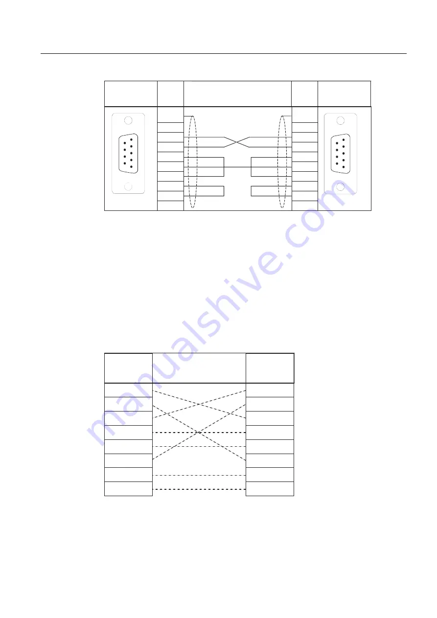
Figure 5-6
Assembly of the standard connecting cable 6NH7701-0AR
Connecting cables for connecting to Ethernet
There is no standard connecting cable available in the SINAUT range to connect the
TIM 4R-IE to Ethernet. Use the suitable Ethernet connecting cables (for example
IE TP Cord) from the SIMATIC NET product range (catalog IK PI).
If a TIM 4R IE is connected to a hub, switch or router, it is advisable to use fully shielded
straight-through patch cables with RJ-45 connectors. The cable must be suitable for the
10Base-TX or 100Base-TX specification.
Two Ethernet TIMs (TIM 4R-IE, TIM 3V-IE variant) can also be connected over Ethernet as a
point-to-point link using a crossover patch cable with RJ-45 connectors at both ends and the
following pinout:
7;'
7;'
5;'
5;'
7;'
7;'
5;'
5;'
3LQQR
6LJQDO
3LQQR
6LJQDO
,QWHUFRQQHFWLRQ
Figure 5-7
Pinout of a crossover Ethernet RJ-45 cable
The cable must be suitable for the 10Base-TX or 100Base-TX specification.


