Siemens SICAM Скачать руководство пользователя страница 74

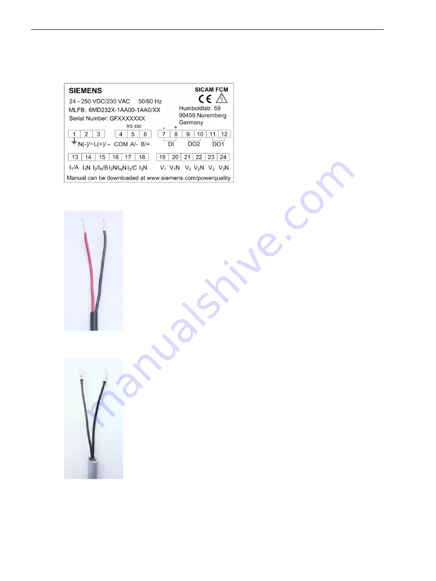
Sensor Connections

The following table shows how the current and voltage sensors are designated as per the terminals.

[dw_sfcmtrml, 2, en_US]

Figure 7-7

Terminal Diagram

[ph_current_sensor_wires, 1, --_--]

Figure 7-8

Phase-Current Sensors Cable Leads (Red/Black)

[ph_voltage_sensor_wires, 1, --_--]

Figure 7-9

Phase-Voltage Sensors Cable Leads (Black/Brown)

7.3

Connection Diagrams
7.3 Sensor Connections

74

SICAM, Feeder Condition Monitor, Manual

E50417-H8940-C580-A4, Edition 03.2019

Содержание SICAM

Страница 1: ...17 H8940 C580 A4 Preface Open Source Software Table of Contents Delivery 1 Introduction 2 Hardware Components and Drawings 3 Device Functions 4 Technical Data 5 Type Testing 6 Connection Diagrams 7 Parameterization A Modbus Registers B Glossary Index ...

Страница 2: ...f business relations nor does it change these All obligations of Siemens AG are stated in the relevant contractual agree ments Siemens AG reserves the right to revise this document from time to time Document version E50417 H8940 C580 A4 01 Edition 03 2019 Version of the product described V03 30 Copyright Copyright Siemens AG 2019 All rights reserved The disclosure duplication distribution and edit...

Страница 3: ...or use within specified voltage limits Low Voltage Directive 2014 35 EU as well as restriction on usage of hazardous substances in electrical and electronic equipment RoHS Direc tive 2011 65 EU This conformity has been proved by tests performed according to the Council Directive and in accordance with the generic standard IEC EN 61326 1 for EMC directive and with the standards IEC EN 61010 1 and I...

Страница 4: ...comprises important information that must be followed for personal safety as well as to avoid material damage Information is highlighted and illustrated as follows according to the degree of danger DANGER DANGER means that death or severe injury will result if the measures specified are not taken Comply with all instructions in order to avoid death or severe injuries WARNING WARNING means that dea...

Страница 5: ...pends on the following Proper transport Proper storage setup and installation Proper operation and maintenance When electrical equipment is operated hazardous voltages are inevitably present in certain parts If proper action is not taken death severe injury or property damage can result The equipment must be grounded at the grounding terminal before any connections are made All circuit components ...

Страница 6: ... of danger ISO 7000 0434 8 Protective Insulation IEC 60417 5172 Safety Class II devices 9 Guideline 2002 96 EC for electrical and electronic devices 10 Guideline for the Eurasian Market Preface 6 SICAM Feeder Condition Monitor Manual E50417 H8940 C580 A4 Edition 03 2019 ...

Страница 7: ...ce Software is licensed royalty free Insofar as the applicable Open Source Software License Conditions provide for it you can order the source code of the Open Source Software from your Siemens sales contact against payment of the shipping and handling charges for a period of at least 3 years since purchase of the Product We are liable for the Product including the Open Source Software contained i...

Страница 8: ...8 SICAM Feeder Condition Monitor Manual E50417 H8940 C580 A4 Edition 03 2019 ...

Страница 9: ...rection Factors for LoPo VT and LoPo CT IEC 61869 10 IEC 61869 11 38 4 1 11 Power Flow Direction Reversal 39 4 1 12 P Q Sign 39 4 1 13 3 Phase Angle Calculations 40 4 1 14 Phase Sequence Monitoring 40 4 1 15 Determination of Fault Direction 41 4 1 16 Direction Determination of Phase Elements 42 4 1 17 Directional Ground Fault Compensated Resonant Grounded 43 4 1 18 Directional Ground Fault in Isol...

Страница 10: ...ttery Freshness Mode 59 5 Technical Data 61 5 1 Device Technical Data 62 6 Type Testing 65 6 1 Type Testing 66 7 Connection Diagrams 69 7 1 Connection Diagrams 70 7 2 Installing the Device 73 7 3 Sensor Connections 74 7 4 Modbus Connection of SICAM FCM with RTU 78 A Parameterization 81 A 1 Parameterization 82 A 2 Parameterizing the User Interface 83 A 3 Editing the Device Settings 91 B Modbus Regi...

Страница 11: ...Delivery 1 1 Delivery 12 1 SICAM Feeder Condition Monitor Manual 11 E50417 H8940 C580 A4 Edition 03 2019 ...

Страница 12: ...thium metal cell 0 6 g lithium content meets the preconditions of Special Provision 188 of the UN Recommendations on the Transport of Dangerous Goods 17th revised edition and is classified according to ADR RID ADN IMDG Code UN 3091 lithium metal batteries contained in equipment 9 preconditions of SP 188 ICAO TI IATA DGR UN 3091 lithium metal batteries contained in equipment 9 preconditions of Sect...

Страница 13: ...Introduction 2 1 Overview 14 2 2 Environmental Protection Hints 20 2 SICAM Feeder Condition Monitor Manual 13 E50417 H8940 C580 A4 Edition 03 2019 ...

Страница 14: ...t ranges from 0 4 kV to 36 kV SICAM FCM measures the RMS value for alternating voltage alternating current and power frequency SICAM FCM calculates the active power P reactive power Q apparent power S power factor cos φ phase angle energy and other relevant values SICAM FCM consists of the following hardware interfaces 3 current inputs 3 voltage inputs 1 digital input 2 digital outputs 1 RS 485 in...

Страница 15: ...perated inside an enclosed dry room To mount SICAM FCM in the panel proceed as follows Cut a rectangle in the Ring Main Unit RMU panel measuring 92 0 mm 0 8 mm 45 0 0 8 mm W H Carry out all the required internal wiring connections For more information about terminal diagrams refer to 3 2 Terminal Diagram Flush SICAM FCM into the panel and lock it with the clamps For more information about installa...

Страница 16: ... 5 1 digital input 2 digital outputs Modbus RTU The mandatory interface cable 6MD2322 0AA80 0AB3 for linkage to the Voltage Detection System VDS has to be ordered separately 6MD2322 1AA00 1AA0 XX1 Voltage Detection System VDS Interface Cable 4 wire connection lead with integrated protection circuit to connect SICAM FCM 6MD2322 1AA00 1AA0 CC with the LRM voltage detection system 1 ground input Leng...

Страница 17: ... mm GOST certificate 6MD2320 0AF00 1AA1 Voltage Sensor 10 kV 10 kV 3 3 25 3 Accuracy class 1 IEC 60044 7 for symmetrical T connectors with C cone for cables Nexans K 440TB Cellpack CTS S Südkabel SEHDT13 and SEHDT23 Voltage factor 1 2 VN Voltage factor 1 9 VN for maximum of 8 hours 6MD2320 0AA04 1AA0 Voltage Sensor 10 kV 10 kV 3 3 25 3 Accuracy class 1 IEC 60044 7 for asymmetric T connectors of nk...

Страница 18: ... Connect ing cable SICAM FCM For resistive voltage dividers conventional VTs and 230 V Fault indicator with direc tional information and measurements of V I f P Q S cos φ power flow direction 2 digital outputs 6MD2321 1AA00 1AA0 XX1 1 x 1 x 1 x 1 x SICAM FCM For voltage detecting systems Fault indicator with direc tional information and measurements of V I f P Q S cos φ and power flow direction 2 ...

Страница 19: ...rmware V03 XX only The device with MLFB number 6MD2321 1AA00 1AA0 CC must be loaded with firmware V02 XX only i i NOTE The device with MLFB number 6MD2322 1AA00 1AA0 CC and above must be loaded with firmware V03 XX only The device with MLFB number 6MD2322 1AA00 1AA0 BB must be loaded with firmware V02 XX only Accessories You can download the current version of the SICAM FCM manual from Siemens Pow...

Страница 20: ...ent any potential negative effects on human health and the environment i i NOTE Our products and batteries must not be disposed of as household waste For disposing batteries it is neces sary to observe the local national international directives Disposal of Mobile Storage Devices e g USB Sticks and Memory Cards When disposing of transferring mobile storage devices using the format or delete functi...

Страница 21: ...Hardware Components and Drawings 3 1 Hardware Components 22 3 2 Terminal Diagram 23 3 3 Dimensional Drawings 25 3 SICAM Feeder Condition Monitor Manual 21 E50417 H8940 C580 A4 Edition 03 2019 ...

Страница 22: ...LEDs The device consists of 3 LEDs which indicate the status of the process FAULT Red Indicates when any distribution system fault is detected COM Yellow Indicates that the communication is active between Modbus master and the SICAM FCM RUN Green Indicates the healthy condition of the device and operating on the auxiliary voltage Digital Input The device consists of 1 digital input for resetting t...

Страница 23: ...Digital input 8 DI1 Digital input 9 DO2 Digital output 2 10 DO2 Digital output 2 11 DO1 Digital output 1 12 DO1 Digital output 1 13 I1 A Phase current I1 14 I1N Neutral 15 I2 IN B Phase current I2 or ground current IN 16 I2 INN Neutral 17 I3 C Phase current I3 18 I3N Neutral 19 V1 Voltage input V1 20 V1N5 Neutral 21 V2 Voltage input V2 22 V2N5 Neutral 23 V3 Voltage input V3 24 V3N5 Neutral 3 2 5 V...

Страница 24: ...al details of the different connection methods Table 3 2 Spring Cage Connection Connection Elements Specifications Connection method Spring cage Conductor size solid 4 0 mm2 Conductor size stranded 2 5 mm2 Stripping length 8 0 mm AWG max 12 0 AWG min 24 0 Table 3 3 Screw Connection Connection Elements Specifications Connection method Screw connection Conductor size solid 1 0 mm2 Conductor size str...

Страница 25: ...ew le_sfcmrearview 1 _ Figure 3 3 Rear View with Terminals 1 Power supply 2 Modbus 3 Digital input 4 Digital output 2 5 Digital output 1 6 Voltage input 7 Current input 3 3 Hardware Components and Drawings 3 3 Dimensional Drawings SICAM Feeder Condition Monitor Manual 25 E50417 H8940 C580 A4 Edition 03 2019 ...

Страница 26: ...en_US Figure 3 4 Front View Isometric View dw_fcm_iso_view 1 en_US Figure 3 5 Isometric View Hardware Components and Drawings 3 3 Dimensional Drawings 26 SICAM Feeder Condition Monitor Manual E50417 H8940 C580 A4 Edition 03 2019 ...

Страница 27: ...m1aadap 231015 1 _ Figure 3 6 1 A 5 A Adaptor 1 Threaded stud 2 CT adaptor PCB 3 Cable assembly Hardware Components and Drawings 3 3 Dimensional Drawings SICAM Feeder Condition Monitor Manual 27 E50417 H8940 C580 A4 Edition 03 2019 ...

Страница 28: ...6MD2322 0AA80 0AB3 necessary for 6MD2322 1AA00 1AA0 3 Orientation of connecting cable to SICAM FCM voltage input terminals 4 SICAM FCM voltage input terminals 5 Connecting cable L1 L2 L3 ground 6 Voltage detection system Hardware Components and Drawings 3 3 Dimensional Drawings 28 SICAM Feeder Condition Monitor Manual E50417 H8940 C580 A4 Edition 03 2019 ...

Страница 29: ...Device Functions 4 1 Description 30 4 SICAM Feeder Condition Monitor Manual 29 E50417 H8940 C580 A4 Edition 03 2019 ...

Страница 30: ...wing criteria Overcurrent detection for phase currents I I and ground current IN Ground current and neutral point displacement voltage IN and VNG for resonant grounded isolated system where VNG is an internally calculated value You can configure the individual time delay setting for phase current and ground currents Table 4 2 Timer Configuration tI Timer for the low set current threshold I tI Time...

Страница 31: ...about ground fault detection by watt metric method refer to chapter 4 1 20 Ground Fault Detection with Cos φ Sin φ Measurement i i NOTE For solid ground or if Idir is set to 0 Idir is disabled and only IN is used for detecting the ground fault i i NOTE For solid ground or if VNG is set to 0 VNG is disabled and only IN IN Watt metric is used for detecting the ground fault Device Functions 4 1 Descr...

Страница 32: ... Fault Detection menu and Table A 3 for the Fault Parameters Ground Fault Detection menu Fault Reset Mechanism The fault status of the device can be reset through anyone of the following mechanisms Auto reset as per user defined time setting Digital input DC 24 V to DC 60 V User interface through keypad Reset RS485 Modbus interface The following logic diagram shows the fault reset mechanism lo_sfc...

Страница 33: ... values below 6 kV phase to ground or 5 A respectively The fault is indicated if the absence of voltage or current persists until the timer T2 elapses T2 T1 For the ground fault configure the threshold for the neutral point displacement voltage VNG and the ground current IN If the threshold exceeds the setting and the fault persists for the times tIN and tVNG the device indicates the ground fault ...

Страница 34: ... 20 Ground Fault Detection with Cos φ Sin φ Measurement i i NOTE For solid ground or if Idir is set to 0 Idir is disabled and only IN is used for detecting the ground fault i i NOTE For solid ground or if VN is set to 0 VNG is disabled and only IN IN Watt metric is used for detecting the ground fault The following logic diagram illustrates the fault indication and fault reset Device Functions 4 1 ...

Страница 35: ...cation and Fault Reset The following figure describes the timer based fault indication operation lo_medvolsup 2 en_US Figure 4 7 Timer Based Fault Indication Device Functions 4 1 Description SICAM Feeder Condition Monitor Manual 35 E50417 H8940 C580 A4 Edition 03 2019 ...

Страница 36: ...ing 50 A to 2500 A tI Delay setting 40 ms to 60 s I Setting 50 A to 2500 A tI Delay setting 40 ms to 60 s IN Setting 0 4 A to 2000 A tIN Delay setting 40 ms to 60 s Table 4 4 Operate Level Parameter Attribute Value I Operate level 110 of I 5 I Operate level 110 of I 5 Table 4 5 Operate Time Parameter Attribute Value tI Operate time 40 ms 25 ms tI Operate time 40 ms 25 ms Inverse Definite Minimum T...

Страница 37: ... active group and its group parameter from HMI and Modbus by holding register address 42 or by turning ON the coil 12 When the device is indicating a fault you cannot change the active group and its parameters At any time only one selected group of settings is active These parameters are used for detecting the ground fault For more information about the active group switching coil refer to Table B...

Страница 38: ...rent and voltage sensors If any inaccuracies are stable within the measuring range then the overall accuracy of sensors is improved to higher level Sensors which specify individual correction factors on their labels and in routine tests can be configured in SICAM FCM to improve system accuracy Sensors which are used in combination with SICAM FCM and do not have correction factors disable the respe...

Страница 39: ... parameters refer to I1 Power Flow Direction Page 124 Power Flow Direction Reversal for Solidly Grounded System The following power flow direction reversal parameters affect the respective power flow direction fault direc tion and power I1 I2 I3 They also affect the IN angle IN power flow direction and IN fault direction The corrected angles for I1 I2 and I3 are displayed in the Modbus input regis...

Страница 40: ...ry to establish the balanced phase sequence before any calculations In the device V1N is considered as a reference phasor at 0 This phase sequence is needed to relate the calculated phasor angles with reference to the phasor V1N dw_sfcm3phangcalc 1 en_US Figure 4 8 3 Phase Angle Calculations In a standard balanced system all phase to phase voltages are phase to neutral voltages multiplied by 3 and...

Страница 41: ...d then the discrete inputs 33 34 of the Modbus registers are set to 0 If the phase to ground voltage is below the threshold voltage then the phase sequence is displayed as on the HMI and the Modbus register is set to 0 If there are any device alerts and a fault is detected in the system then the phase sequence is displayed as on the HMI and the Modbus register is set to 0 i i NOTE Protection funct...

Страница 42: ...t element has a direction by a voltage derived from the other 2 phases This connection introduces a 90 phase jump current leading voltage between reference voltages and operating quantities currents A fault is determined to be in the selected direction if its phase relationship lies within a quadrant of 85 on either side of the characteristic angle It is hard coded as 45 dw_sfcm dirdetphaelm 1 en_...

Страница 43: ...ent menu dw_sfcm grndflt comp res 1 en_US Figure 4 11 Directional Ground Fault Compensated Resonant Grounded for Vector Method i i NOTE The undetermined area for the device MLFB 6MD2321 1AA00 1AA0 is 10 and the respective angles change accordingly The undetermined area for the device MLFB 6MD2322 1AA00 1AA0 is 20 and the respective angles change accordingly Directional Ground Fault in Isolated Ele...

Страница 44: ...d System The solidly grounded system is a common system arrangement in which the neutral is solidly connected to the ground For the solid grounded connection the neutral point displacement voltage is sufficient to measure and determine the directional information This results in determining the ground fault direction based on the rotation angle of the reference vector dw_sfcm grndflt sol 1 en_US F...

Страница 45: ...set threshold IN and Idir respectively and if the time delay tIN is greater than the set threshold the device indicates a fault If Idir is set to 0 vector method irrespective of the selected ground type connection the total ground current is compared with the set current IN for fault detection For resonant ground connections if Idir is not 0 ground fault detection with cos φ sin φ measurement meth...

Страница 46: ...plicable for resonanlt grounded systems only and not applicable to the undercompensated systems Figure 4 15 shows a simplified network with the pulse location detection mechanism The pulse pattern in the ground current IN is generated by switching on and off a capacitor in parallel to the arc suppression coil When the capacitor is switched on an additional capacitive ground current is generated an...

Страница 47: ... faults the pulse pattern exists only in the faulty feeder For high impedance ground faults the pulse pattern is also present in the healthy feeders with lower amplitude but in phase opposition to the faulty feeder Using different values of the parameters Pulse on duration TPulse ON and Pulse off duration TPulse OFF the differentiation between healthy and faulty feeders for high impedance ground f...

Страница 48: ... switch off duration of the capacitor If you set these 2 parameters to the same value or to similar values there is a risk of failure This is the case because the stage cannot distin guish the healthy and faulty feeders by only evaluating the ground current during a high impedance ground fault Number of Pulses for Operate PulseTh Op is defined as the number of pulses to be detected within the puls...

Страница 49: ...l outputs opens for 100 ms and closes again afterwards For every phase fault the Modbus register Address 24 is set for 3 s or until the fault current persists If the fault current does not persist the Modbus register is reset for 3 s This logic is active only if the DOs are not configured For more information about the Modbus register refer to Table B 11 Intermittent Ground Fault A typical charact...

Страница 50: ...rossBlockTimer value then the device displays a fault indication The device does not block the fault indication if the fault current is above the set threshold I for the time tI If the fault current persists for the respective time setting tI for phases tIN for ground the inrush current blocking function monitors the inrush current The inrush current is detected by analyzing the magnitude of the 2...

Страница 51: ...s connected to the I2 IN terminal the ground current can be measured for isolated resonant grounded systems When the ground current is measured the ground current can be configured from 25 A to 150 A For more information about the ground sensor refer to Ground Sensor Page 123 The calculation measurement of the ground current is determined by setting the Ground current acquisition parameter i i NOT...

Страница 52: ... a 20 kV sensor is used in the 10 kV system set the primary voltage equal to 10 kV and the sensor rated voltage equal to 20 kV i i NOTE When the device with firmware version 2 00 2 10 is upgraded to firmware version 2 20 and above check the Primary voltage and Sensor voltage parameters and adapt them accordingly Voltage Measurements with Sensors as per IEC 60044 7 IEC 61869 11 and with Conventiona...

Страница 53: ...nnected to the secondary side of the transformer in the LV system and the current inputs I1 I2 and I3 of the device are connected to the LoPo current sensors in the medium voltage system The figure illustrates the transformer type Dy 11 used in the medium voltage low voltage measurement For more information about transformer types refer to Transformer Type Page 114 dw_sfcm_mv_lv_measurement 2 en_U...

Страница 54: ...aptor dw_sfcm volmsrmtVDS 2 en_US Figure 4 22 SICAM FCM Voltage Measurement in VDS The capacitances C1 and C2 are located internally to the RMU bushing and in the VDS device respectively When the device is connected for the first time as per the scheme you must calibrate the device via the HMI or Modbus to get the accurate voltage measurements Auto Calibration You must calibrate the device when it...

Страница 55: ...ion about these counters refer to 3 Phase Active Import Energy Counter Page 139 The counter value can be reset by any one of the following methods Using the Energy counter reset parameter via HMI Using the Energy counter reset Modbus register For more information refer to Table B 10 RTC Synchronization The device provides an internal real time clock In order to get an external time synchronization...

Страница 56: ... least once after the remote firmware update is completed i i NOTE For updating the firmware via the SICAM FCM Configurator tool refer to the SICAM FCM Configurator Manual i i NOTE The fault LED red color of the device blinks during the firmware download It takes around 10 minutes to complete the firmware download i i NOTE When CMIC is connected to multiple SICAM FCM devices refer to the Readme fo...

Страница 57: ...ommunicated via Modbus and displayed on the user interface The alerts reset automatically when the current voltage falls below the threshold levels again or exceeds them again in case of an undervoltage Undervoltage Alarm and Undervoltage Warning The undervoltage alerts are enabled when the system voltage falls below the user defined setting Vmin Alarm Vmin Warning The threshold is defined in perc...

Страница 58: ...TE If you set the threshold for an undervoltage alarm Vmin Alarm undervoltage warning Vmin Warning over voltage alarm Vmax Alarm and overvoltage warning Vmax Warning closer to the primary voltage and if a frequency change occurs 0 2 Hz a false indication of the undervoltage alarm undervoltage warning overvoltage alarm and overvoltage warning can occur i i NOTE The overvoltage alarm warning resets ...

Страница 59: ...lecting the BFM mode the device stops all the routine operations until the power supply is reconnected i i NOTE If the device is temporarily connected to the auxiliary voltage only activate the BFM mode every time before switching off the auxiliary voltage to avoid discharge of the battery To enable BFM in the device proceed as follows In the Home Screen press the BFM key The Battery freshness men...

Страница 60: ...enabling the Battery Freshness Mode then Device HMI displays the message Battery is being discharged enable battery freshness mode and The Fault LED Red and Communciation LED Yellow flash for 30 min Device Functions 4 1 Description 60 SICAM Feeder Condition Monitor Manual E50417 H8940 C580 A4 Edition 03 2019 ...

Страница 61: ...Technical Data 5 1 Device Technical Data 62 5 SICAM Feeder Condition Monitor Manual 61 E50417 H8940 C580 A4 Edition 03 2019 ...

Страница 62: ... 20 kΩ Measuring range phase current 225 mV 300 A sensor 1 A to 6000 A Measuring range ground current 225 mV 60 A sensor 0 2 A to 1200 A Thermal load capacity current inputs 4 5 Vrms continuous Measured Value Accuracy Measured Variable Accuracy Class Depending on IEC 61557 12 2007 08 K55 Voltage V8 0 5 1 for MLFB 6MD2322 1AA00 1AA0 for secondary VDS voltage at 30 V Phase current I9 1 A or 0 5 at r...

Страница 63: ...ent ratio of 60 A primary 0 1 A for current range 0 2 A to 1 A 0 25 A for current range 1 A to 49 A 10 for current range 1 1 A to 15 A 1 for current range 50 A to 1200 A i i NOTE For grounded systems the accuracy of the calculated ground current is 3 i i NOTE The device parameter for ground fault detection IN ranges from 0 4 A to 2000 A The accuracy of meas urements differs based on the threshold ...

Страница 64: ...0 g Environment Operating temperature range 40 C to 70 C Storage temperature range 25 C to 55 C Humidity range 0 to 95 non condensing Altitude above sea level Maximum up to 2000 m Protection Device Class Device front IP 40 Device rear IP 20 Power Consumption DC 24 V AC 230 V 0 8 W Peak power during power on 6 0 W i i NOTE When the auxiliary power supply fails the device is switched on with an inte...

Страница 65: ...Type Testing 6 1 Type Testing 66 6 SICAM Feeder Condition Monitor Manual 65 E50417 H8940 C580 A4 Edition 03 2019 ...

Страница 66: ...e test IEC 61010 1 IEC 61010 2 30 Insulation test between auxiliary power supply terminals L N communication channels DI DO connected together and ground all voltage current channels connected together Insulation test between auxiliary power supply terminals L N and all DI DO terminals connected together Insulation test between communication chan nels and DI terminals 2 5 kV 4 kV Insulation test b...

Страница 67: ... Criteria B Electrical fast tran sient burst immunity test IEC 61000 4 4 Level 3 4 kV on auxiliary power supply current inputs voltage inputs digital input and digital outputs 2 kV on communication port Surge immunity test IEC 61000 4 5 Level 3 IEC 61326 1 Level 3 2 kV DM 4 kV CM on auxiliary power supply and voltage inputs 1 kV DM 2 kV CM on digital input and digital outputs 4 kV on current input...

Страница 68: ...z to 30 MHz Class A Disturbance field strength radiated emission CISPR 11 CISPR 32 30 MHz to 1 GHz Class A 1 GHz to 6 GHz Ingress Protection of Enclosure Table 6 7 Ingress Protection Tests Standard Test Requirements Degree of protection IEC 60529 IP40 for front side IP20 for rear side Type Testing 6 1 Type Testing 68 SICAM Feeder Condition Monitor Manual E50417 H8940 C580 A4 Edition 03 2019 ...

Страница 69: ...agrams 7 1 Connection Diagrams 70 7 2 Installing the Device 73 7 3 Sensor Connections 74 7 4 Modbus Connection of SICAM FCM with RTU 78 7 SICAM Feeder Condition Monitor Manual 69 E50417 H8940 C580 A4 Edition 03 2019 ...

Страница 70: ...ted ground fault indicator by using the ground current sensor The following scheme shows how the device works as a non directional ground fault indicator 50 G dw_sfcm_grdfltindi 2 en_US Figure 7 2 SICAM FCM as Ground Fault Indicator Fault Detector The device can be used as a fault detector by providing fault information with directional information This requires an additional low power voltage tra...

Страница 71: ...sors are connected to the current inputs I1 I2 and I3 These connec tion diagrams are used for a solidly grounded system and the IN value is calculated dw_sfcm fltdtct nonvt 2 en_US Figure 7 4 SICAM FCM as Fault Detector 3 Low Power Voltage Transformer and Current Transformer with 3 Phase Currents for MLFB 6MD2322 1AA00 1AA0 3 Low Power Voltage Sensor 2 Phase Current and Sensitive Ground Current Se...

Страница 72: ...sfcm fltdtct capsnt 2 en_US Figure 7 6 SICAM FCM as Fault Detector 3 Low Power Voltage Transformer with 2 Phase Currents and Sensitive Ground Current Sensor for MLFB 6MD2322 1AA00 1AA0 i i NOTE During electrical installation all the rules and regulations of power systems must be observed Low Voltage 230 V Measurement For more information about low voltage 230 V measurement see chapter 4 1 30 Low V...

Страница 73: ...the operating environment for at least 2 hours to avoid humidity and condensation problems i i NOTE Ensure that the terminal 1 of the device is properly grounded with the ground wire provided i i NOTE If the device is commissioned after a long period of time make sure to run a power ON OFF sequence and keep the device in the OFF condition for an hour 7 2 Connection Diagrams 7 2 Installing the Devi...

Страница 74: ... 2 en_US Figure 7 7 Terminal Diagram ph_current_sensor_wires 1 _ Figure 7 8 Phase Current Sensors Cable Leads Red Black ph_voltage_sensor_wires 1 _ Figure 7 9 Phase Voltage Sensors Cable Leads Black Brown 7 3 Connection Diagrams 7 3 Sensor Connections 74 SICAM Feeder Condition Monitor Manual E50417 H8940 C580 A4 Edition 03 2019 ...

Страница 75: ...low the instructions of the sensors you use Power Flow Direction The following figure shows the power flow direction from P1 to P2 le_sfcm_powflodir 160624 1 _ Figure 7 10 Power Flow Direction from P1 to P2 1 Power Flow Direction from P1 to P2 Table 7 2 Power Flow Direction Parameters for Solidly Grounded Systems Phase Parameter Value I1 power flow direction Not reversed I2 IN power flow direction...

Страница 76: ...ion Not reversed i i NOTE Table 7 2 and Table 7 3 show the settings recommended by Siemens You can change the power flow direction according to your applications Current Sensors Grounding Connection dw_sfcm_cursen_grndconn 1 en_US Figure 7 11 Current Sensors Grounding Connection Connection Diagrams 7 3 Sensor Connections 76 SICAM Feeder Condition Monitor Manual E50417 H8940 C580 A4 Edition 03 2019...

Страница 77: ...age Sensors Grounding Connection i i NOTE Always ensure that the protective ground terminal 1 of SICAM FCM is grounded in the RMU panel with a short cable size 2 5 mm2 Connection Diagrams 7 3 Sensor Connections SICAM Feeder Condition Monitor Manual 77 E50417 H8940 C580 A4 Edition 03 2019 ...

Страница 78: ...ion_fcm rtu 1 en_US Figure 7 13 SICAM FCM Modbus Connection with RTU Table 7 4 Modbus Connection with RTU SICAM CMIC A8000 SICAM FCM Pin Assignment Interface X3 Terminal 4 5 A Terminal 5 6 B Terminal 6 4 COM 0 V 7 4 Connection Diagrams 7 4 Modbus Connection of SICAM FCM with RTU 78 SICAM Feeder Condition Monitor Manual E50417 H8940 C580 A4 Edition 03 2019 ...

Страница 79: ...en_US Figure 7 14 Modbus Connection with SICAM FCM and MCU The following S2 DIP switch settings show the mode of operation of RS485 on MCU S2 2 S2 1 Description OFF OFF 2W No bus termination OFF ON 2W With bus termination Connection Diagrams 7 4 Modbus Connection of SICAM FCM with RTU SICAM Feeder Condition Monitor Manual 79 E50417 H8940 C580 A4 Edition 03 2019 ...

Страница 80: ...ng and Grounding Connection Modbus Termination dw_modbus_termination 2 en_US Figure 7 16 Modbus Termination i i NOTE SICAM FCM has no internal Modbus load resistor If SICAM FCM is located at the end of the Modbus connec tion use an external resistor for Modbus termination Connection Diagrams 7 4 Modbus Connection of SICAM FCM with RTU 80 SICAM Feeder Condition Monitor Manual E50417 H8940 C580 A4 E...

Страница 81: ...Parameterization A 1 Parameterization 82 A 2 Parameterizing the User Interface 83 A 3 Editing the Device Settings 91 A SICAM Feeder Condition Monitor Manual 81 E50417 H8940 C580 A4 Edition 03 2019 ...

Страница 82: ...r area contains the respective menu navigation functions You can navigate through the menu using the keypads by selecting a value or editing the device settings The following functions are assigned to the navigation keys Battery Freshness Mode BFM Enables the Battery Freshness Mode For more information refer to 4 1 39 Battery Freshness Mode MENU Calls the main menu OK Opens the submenu from the se...

Страница 83: ...h the keys you can view the following parameters Phase to phase voltages 1 phase active power 1 phase reactive power 1 phase apparent power 3 phase active power 3 phase reactive power 3 phase apparent power Phase sequence Zero sequence voltage Positive sequence voltage Negative sequence voltage The default menu also displays the power flow direction and status of the feeder A 2 Parameterization A ...

Страница 84: ...parameterization menu structure displays the main menu and the relevant submenu functions Table A 1 Parameters Menu Structure MENU EVENTS TRAILING POINTERS Parameterization A 2 Parameterizing the User Interface 84 SICAM Feeder Condition Monitor Manual E50417 H8940 C580 A4 Edition 03 2019 ...

Страница 85: ...0 to disable the detection function SAVE PHASE FAULT DETECTION tI 0 04 s to 60 s SAVE PHASE FAULT DETECTION I 50 A to 2500 A Set to 0 to disable the detection function SAVE PHASE FAULT DETECTION tI 0 04 s to 60 s SAVE Table A 3 Parameters Menu Structure Fault Parameters FAULT PARAME TERS GROUND FAULT DETECTION IN ACTIVE GROUP GROUP 1 GROUP 2 SAVE SAVE GROUND FAULT DETECTION IN GROUP1 SETTING GROUN...

Страница 86: ...60 s SAVE Idir 0 2 A to 30 A Set to 0 to disable the cos ϕ sin ϕ method SAVE NEUTRAL POINT TREATMENT SOLID or ISOLATED or RESO NANT SAVE V 0 to 100 Set to 0 to disable the detection function SAVE V 0 to 170 Set to 0 to disable the detection function SAVE PULSE DETEC TION 3I0 DELTA 0 to 300 Set to 0 to disable the detection function SAVE PULSE DETEC TION TPULSE ON 0 50 s to 20 s Set to 0 to disable...

Страница 87: ...LTAGE ALERTS UNDER VOLTAGE WARNING 0 to 30 Set to 0 to disable the undervoltage warning SAVE UNDER VOLTAGE ALARM 0 to 30 Set to 0 to disable the undervoltage alarm SAVE OVERCURRENT ALERTS OVERCURRENT WARNING 50 A to 2000 A Set to 0 to disable the detection function SAVE OVERCURRENT ALARM 50 A to 2000 A Set to 0 to disable the detection function SAVE OVERCURRENT TWARNING 1 min to 120 min Set to 0 t...

Страница 88: ...GE PARAMETERS LV TO MV CALCU LATION TRANSFORMER TYPE DY 11 TRANSFORMER ANGLE 0 to 359 SAVE PRIMARY VOLTAGE CORRECTION 0 V to 900 V SAVE CAPACITIVE VOLTAGE MEAS UREMENT AUTO CALIBRA TION VOLTAGE 1000 V to 36000 V SAVE AUTO CALIBRA TION START AUTO CALI BRATION OK RATED SEC VOLTAGE AC 3 25 3 or AC 100 3 V or AC 230 V or AC 400 3 SAVE RATED PRI VOLTAGE 1 0 kV to 36 0 kV SAVE SENSOR VOLTAGE PRIMARY 1 0...

Страница 89: ...D CURR ACQUISITION MEASUREMENT OR CALCULATION SAVE CURRENT CORREC TION FACTOR I1 MAGNITUDE FACTOR I1 ANGLE OFFSET I2 IN MAGNITUDE FACTOR I2 IN ANGLE OFFSET I3 MAGNITUDE FACTOR I3 ANGLE OFFSET FREQUENCY 50 Hz or 60 Hz SAVE ENERGY COUNTER RESET PRESS OK OK P Q SIGN NOT REVERSED REVERSED SAVE Table A 6 Parameters Menu Structure DO Configuration DO CONFIGURATION FAULT DIRECTION OR DEVICE HEALTH SAVE P...

Страница 90: ...E NOW 0 to 23 0 to 59 0 to 59 SAVE DATE AND TIME TIME FORMAT NEW TIME FORMAT 12 HOUR or 24 HOUR SAVE VERSION INFORMA TION ACTIVE FIRMWARE VERSION INFORMATION IS DISPLAYED SELF TEST ACTIVATES SELF TEST PASSWORD PROTEC TION DISABLE OR ENABLE SAVE CHANGE PASSWORD ENTER NEW PASSWORD i i NOTE The device resets if one of the following parameters is changed Frequency Neutral point treatment Baud rate Par...

Страница 91: ...New I menu appears In the New I menu press the up arrow or the down arrow to set the New I value within the desired range Press Save to save the new Phase Fault Detection I value i i NOTE To navigate from one value to another value use the left arrow and right arrow For entering values for example from 0 A to 2500 A press the up arrow or the down arrow Press Esc if you want to cancel the edit mode...

Страница 92: ...92 SICAM Feeder Condition Monitor Manual E50417 H8940 C580 A4 Edition 03 2019 ...

Страница 93: ...egister Type Data Holding Registers 110 B 5 Register Type Data Input Registers 131 B 6 Register Type Data Analog Input Registers 144 B 7 Register Type Data Events 150 B 8 Register Type Data Trailing Pointers 153 B 9 Self Test Mode 156 B SICAM Feeder Condition Monitor Manual 93 E50417 H8940 C580 A4 Edition 03 2019 ...

Страница 94: ...rom the master The device works as Modbus Slave and supports communication via RS485 Regard less of the transmission mode the communication cycle and contents remain the same The message frame contains the following format Device address Function code 8 bit data bytes Error checking The following Modbus data models are supported Bit type data Discrete input Coil Register type data Input register H...

Страница 95: ...ion code it returns the exception code response as 01 Data Package Format Table B 1 Communication Settings Baud rate bps 2400 4800 9600 19200 38400 57600 115200 Parity O E N Table B 2 Modbus Parameters Modbus ID 1 to 247 0 Broadcast 248 to 255 Special Modbus type RTU In the SICAM FCM the data byte standard setting is as follows 1 start bit 8 data bits LSB first 1 parity bit odd even none 1 stop bi...

Страница 96: ...larm Vmax Alarm R 7 Discrete Input Undervoltage warning Vmin Warning R 8 Discrete Input Undervoltage alarm Vmin Alarm R 9 Discrete Input I I direction A R 10 Discrete Input I I direction B R 11 Discrete Input IN direction A R 12 Discrete Input IN direction B R 13 Discrete Input Forward A power flow direction of I1 R 14 Discrete Input Reverse B power flow direction of I1 R 15 Discrete Input Forward...

Страница 97: ...ent trip value I high set 0 A uInt16 12 4 to 6000 Overcurrent response time tI 4 x 10 ms uInt16 13 0 4 to 20000 Ground fault trip value IN Group 1 0 1 10 A uInt16 14 4 to 6000 Ground fault response time tIN Group 1 4 x 10 ms uInt16 15 2 Transformer type 2 uInt16 16 0 to 2 Neutral point treatment Group 1 2 uInt16 17 0 to 4 Language 1 uInt16 18 0 to 3 Voltage transformer secondary low power voltage ...

Страница 98: ...uInt16 50 0 to 1 Ground current acquisition 0 uInt16 51 0 to 1 DO configuration 0 uInt16 52 Reserved for future use 53 Reserved for future use 54 0 to 60000 Crossblocktimer 100 ms uInt16 55 25 to 150 Ground sensor 60 A uInt16 56 0 to 1 I1 power flow direction 0 uInt16 57 0 to 1 I2 IN power flow direction 1 uInt16 58 0 to 1 I3 power flow direction 0 uInt16 59 0 to 1 P Q sign 0 uInt16 60 0 to 2 Neut...

Страница 99: ...000 85 500 to 500 V3 angle offset 0 min Int16 86 0 800 to 1200 I1 magnitude factor correction factor disabled 0 1 1000 ulnt16 I1 magnitude factor correction factor enabled 1000 87 500 to 500 I1 angle offset 0 min Int16 88 0 800 to 1200 I2 IN magnitude factor correction factor disabled 0 1 1000 ulnt16 I2 IN magnitude factor correction factor enabled 1000 89 500 to 500 I2 IN angle offset 0 min Int16...

Страница 100: ...r 230 V sensor uInt16 1 100 kV for 3 25 3 sensor for 100 3 sensor and for 400 3 sensor 1007 0 to 65535 Voltage V1 1 10 V for 230 V sensor uInt16 1 100 kV for 3 25 3 sensor for 100 3 sensor and for 400 3 sensor 1008 0 to 65535 Voltage V2 1 10 V for 230 V sensor uInt16 1 100 kV for 3 25 3 sensor for 100 3 sensor and for 400 3 sensor 1009 0 to 65535 Voltage V3 1 10 V for 230 V sensor uInt16 1 100 kV ...

Страница 101: ... for 3 25 3 sensor for 100 3 sensor and for 400 3 sensor 1024 1029 1033 32768 to 32767 Reactive power phase 1 reactive power phase 2 reactive power phase 3 1 10 kVAr for 230 V sensor sInt16 1 kVAr for 3 25 3 sensor for 100 3 sensor and for 400 3 sensor 1025 1030 1034 1000 to 1000 Power factor phase 1 power factor phase 2 power factor phase 3 1 1000 sInt16 1026 0 to 65535 Frequency 1 100 Hz uInt16 ...

Страница 102: ...47 Active import energy 1 kWh for 230 V sensor uInt32 1046 1 MWh for 3 25 3 sensor for 100 3 sensor and for 400 3 sensor 1047 2 147 483 648 to 2 147 483 647 Active export energy 1 kWh for 230 V sensor uInt32 1048 1 MWh for 3 25 3 sensor for 100 3 sensor and for 400 3 sensor 1049 2 147 483 648 to 2 147 483 647 Reactive import energy 1 kVArh for 230 V sensor uInt32 1050 1 MVArh for 3 25 3 sensor for...

Страница 103: ...e milliseconds ms uInt16 8 Overvoltage alarm time hours and minutes h and min uInt16 9 Overvoltage alarm time month and date month and date uInt16 10 Overvoltage alarm time year year uInt16 11 Overvoltage warning type uInt16 12 Overvoltage warning time milliseconds ms uInt16 13 Overvoltage warning time hours and minutes h and min uInt16 14 Overvoltage warning time month and date month and date uIn...

Страница 104: ...np Reg Time in milliseconds ms uInt16 303 to 493 0 to 23 0 to 59 Inp Reg Time in hours and minutes h and min uInt16 304 to 494 1 to 31 1 to 12 Inp Reg Time in month and date month and date uInt16 305 to 495 12 to 99 Inp Reg Time in year year uInt16 306 to 496 0 to 9999 Inp Reg Phase current I1 A uInt16 307 to 497 0 to 9999 Inp Reg Phase current I2 A uInt16 308 to 498 0 to 9999 Inp Reg Phase curren...

Страница 105: ...2 P3 min 45 minutes Q1 Q2 Q3 min 45 minutes S1 S2 S3 min 45 minutes uInt16 166 to 169 170 to 172 173 to 175 176 to 178 Inp Reg I1 I2 I3 IN max 45 minutes P1 P2 P3 max 45 minutes Q1 Q2 Q3 max 45 minutes S1 S2 S3 max 45 minutes uInt16 179 to 182 183 to 185 186 to 188 189 to 191 Inp Reg I1 I2 I3 IN min 60 minutes P1 P2 P3 min 60 minutes Q1 Q2 Q3 min 60 minutes S1 S2 S3 min 60 minutes uInt16 192 to 19...

Страница 106: ...1 month Q1 Q2 Q3 max 1 month S1 S2 S3 max 1 month uInt16 257 to 260 261 to 263 264 to 266 267 to 269 Inp Reg I1 I2 I3 IN min 1 year P1 P2 P3 min 1 year Q1 Q2 Q3 min 1 year S1 S2 S3 min 1 year uInt16 270 to 273 274 to 276 277 to 279 280 to 282 Inp Reg I1 I2 I3 IN max 1 year P1 P2 P3 max 1 year Q1 Q2 Q3 max 1 year S1 S2 S3 max 1 year uInt16 Modbus Registers B 2 Implementation of the Modbus Protocol ...

Страница 107: ...o zero 11 Password reset 1 Reset the password to the default value 1111 only if the password protection is enabled in the device 12 Active group switching 1 Toggles the active group between group 1 and group 2 Table B 11 Bit Type Data Discrete Input Address Bit Type Data Description 1 Status data data available 1 0 New data available No new data available The bit is set to 1 on occurrence of IN I ...

Страница 108: ...f I3 Power flow direction of I3 is not forward A 18 Reverse B power flow direc tion of I3 1 0 Reverse B power flow direction of I3 Power flow direction of I3 is not reverse B 19 Time synchronization required 1 0 No time synchronization in the last 24 hours Device is in time synchronization 20 Overcurrent warning 1 0 Overcurrent warning detected No overcurrent warning detected 21 Overcurrent alarm ...

Страница 109: ...No Phase 3 to ground fault detected 32 Intermittent ground fault indi cation 1 0 Intermittent ground fault detected IN No intermittent ground fault detected IN 33 Phase sequence monitoring 1 0 Clockwise phase sequence ABC detected ACB or no phase sequence detected 34 Phase sequence monitoring 1 0 Counter clockwise phase sequence ACB detected ABC or no phase sequence detected Modbus Registers B 3 B...

Страница 110: ...at 16 bit unsigned integer Range 0 to 6 Baud rate bps 0 1 2 3 4 5 6 2400 4800 9600 19200 38400 57600 115200 Default 6 115200 bps Modbus ID Address 4 This register defines the Modbus ID Bit 15 14 13 12 11 10 9 8 215 214 213 212 211 210 29 28 Bit 7 6 5 4 3 2 1 0 27 26 25 24 23 22 21 20 Format 16 bit unsigned integer Range 1 to 247 Default 247 Date and Time Address 5 to 8 The format used for date and...

Страница 111: ...ed Minutes 27 26 25 24 23 22 21 20 Hours Format 5 bit unsigned integer Unit h Range 0 to 23 Minutes Format 6 bit unsigned integer Unit Min Range 0 to 59 Address 7 Table B 14 Date and Time Date Month Bit 15 14 13 12 11 10 9 8 Not used Month 215 214 213 212 211 210 29 28 Bit 7 6 5 4 3 2 1 0 Not used Date 27 26 25 24 23 22 21 20 Month Format 4 bit unsigned integer Unit Month Range 1 to 12 Date Format...

Страница 112: ...ncy 60 Hz grid frequency Default 0 50 Hz Primary Voltage Address 10 This register contains the primary voltage Bit 15 14 13 12 11 10 9 8 215 214 213 212 211 210 29 28 Bit 7 6 5 4 3 2 1 0 27 26 25 24 23 22 21 20 Format 16 bit unsigned integer Unit 1 10 kV Range 10 to 360 Default 200 For example if Modbus value is 10 1 0 kV 115 11 5 kV Overcurrent Trip Value I high set Address 11 This register defin...

Страница 113: ...value for a ground fault protection Bit 15 14 13 12 11 10 9 8 215 214 213 212 211 210 29 28 Bit 7 6 5 4 3 2 1 0 27 26 25 24 23 22 21 20 Format 16 bit unsigned integer Unit A Range 0 4 to 20000 ground fault settings When 0 is selected then the protection function is disabled Default 0 For example if Modbus value is 4 0 4 A 1000 100 A Ground Fault Response Time tIN Group 1 Address 14 This register d...

Страница 114: ...20 Format 16 bit unsigned integer Range 0 to 2 0 Solid 1 Isolated 2 Compensated Default 2 Resonant Language Address 17 This register defines the device language Bit 15 14 13 12 11 10 9 8 215 214 213 212 211 210 29 28 Bit 7 6 5 4 3 2 1 0 27 26 25 24 23 22 21 20 Format 16 bit unsigned integer Range 0 to 4 0 English 1 Deutsch 2 Español 3 Portugués 4 Français Default 1 Deutsch Voltage Transformer Seco...

Страница 115: ...D Default 0 DD MM YYYY Time Type Address 20 This register defines the time type Bit 15 14 13 12 11 10 9 8 Not used Not used Not used Not used Not used Not used Not used Not used 215 214 213 212 211 210 29 28 Bit 7 6 5 4 3 2 1 0 Not used Not used Not used Not used Not used Not used Not used Time type 27 26 25 24 23 22 21 20 Format 1 bit unsigned integer Range 0 12 hour format 1 24 hour format Defau...

Страница 116: ...e format used is 16 bit unsigned integer VMin Warning Address 24 This register defines the minimum threshold voltage you can set for providing a warning It is expressed in percentage of the primary voltage Refer to VMin Alarm Page 116 The format used is 16 bit signed integer Neutral Point Displacement Voltage VNG Group 1 Address 25 This register defines the neutral point displacement voltage It is...

Страница 117: ...itude threshold VNG the timer tVNG starts counting At any time during the activity if the magnitude falls below the threshold value VNG timer tVNG is reset Rated Primary Current Address 28 This register defines the rated primary current Bit 15 14 13 12 11 10 9 8 215 214 213 212 211 210 29 28 Bit 7 6 5 4 3 2 1 0 27 26 25 24 23 22 21 20 Format 16 bit unsigned integer Unit A Range 50 to 1000 Default ...

Страница 118: ...050 10500 ms Timer T1 Address 31 This register defines the pick up monitoring time Bit 15 14 13 12 11 10 9 8 215 214 213 212 211 210 29 28 Bit 7 6 5 4 3 2 1 0 27 26 25 24 23 22 21 20 Format 16 bit unsigned integer Unit s Range 0 1 to 60 Default 0 Timer T2 Address 32 This register defines the absence of voltage and current monitoring time Bit 15 14 13 12 11 10 9 8 215 214 213 212 211 210 29 28 Bit ...

Страница 119: ...register defines the overcurrent warning The value is expressed in amperes Bit 15 14 13 12 11 10 9 8 215 214 213 212 211 210 29 28 Bit 7 6 5 4 3 2 1 0 27 26 25 24 23 22 21 20 Format 16 bit unsigned integer Unit A Range 50 to 2000 Default 0 When 0 is selected then the Imaxwarning is disabled I Max Alarm Time Setting Address 36 This register defines the overcurrent alarm time The value is expressed ...

Страница 120: ... This register defines the transformer angle Based on the selected transformer type you can set the angle phase shift of the secondary side with respect to the primary side Bit 15 14 13 12 11 10 9 8 215 214 213 212 211 210 29 28 Bit 7 6 5 4 3 2 1 0 27 26 25 24 23 22 21 20 The following table provides the phase shift in degree lag based on the selected transformer type Format 16 bit unsigned intege...

Страница 121: ...ains the active group for ground fault detection Bit 15 14 13 12 11 10 9 8 215 214 213 212 211 210 29 28 Bit 7 6 5 4 3 2 1 0 27 26 25 24 23 22 21 20 Format 16 bit unsigned integer Unit Range 0 to 1 Default 0 Ground Fault Trip Value IN Group 2 Address 43 This register defines the ground current value for a ground fault protection Refer to Ground Fault Trip Value IN Group 1 Page 113 Ground Fault Res...

Страница 122: ...16 bit unsigned integer Unit Range 0 4 V to 30 V Default 0 4 V to 30 V Auto Calibration Voltage Address 49 This register defines the auto calibration voltage Bit 15 14 13 12 11 10 9 8 215 214 213 212 211 210 29 28 Bit 7 6 5 4 3 2 1 0 27 26 25 24 23 22 21 20 Format 16 bit unsigned integer Unit V Range 1000 to 36 000 Default 20 000 Ground Current Acquisition Address 50 This register defines the grou...

Страница 123: ...ication 1 Device health indication Default 0 Fault direction indication Reserved for future use Address 52 Reserved for future use Address 53 CrossBlockTimer Address 54 This register defines the time threshold for blocking of fault indication by inrush current detec tion It is expressed in milliseconds Bit 15 14 13 12 11 10 9 8 215 214 213 212 211 210 29 28 Bit 7 6 5 4 3 2 1 0 27 26 25 24 23 22 21...

Страница 124: ...er defines the I2 IN power flow direction parameter Bit 15 14 13 12 11 10 9 8 215 214 213 212 211 210 29 28 Bit 7 6 5 4 3 2 1 0 27 26 25 24 23 22 21 20 Format 16 bit unsigned integer Range 0 to 1 0 Not reversed 1 Reversed Unit Default 1 Reversed I3 Power Flow Direction Address 58 This register defines the I3 power flow direction parameter Bit 15 14 13 12 11 10 9 8 215 214 213 212 211 210 29 28 Bit...

Страница 125: ...point treatment method Bit 15 14 13 12 11 10 9 8 215 214 213 212 211 210 29 28 Bit 7 6 5 4 3 2 1 0 27 26 25 24 23 22 21 20 Format 16 bit unsigned integer Range 0 to 2 0 Solid 1 Isolated 2 Compensated Default 1 Isolated Reserved for future use Address 61 Reserved for future use Address 62 Reserved for future use Address 63 Reserved for future use Address 64 Reserved for future use Address 65 Reserv...

Страница 126: ...of the network rated voltage Bit 15 14 13 12 11 10 9 8 215 214 213 212 211 210 29 28 Bit 7 6 5 4 3 2 1 0 27 26 25 24 23 22 21 20 Format 16 bit unsigned integer Range 100 to 170 Default 0 IN Delta Pulse Off On 3I0 Delta Address 72 This register defines the threshold value of the ground fault current between pulse ON and pulse OFF This register is set as percentage value of the rated ground current ...

Страница 127: ...fault 0 For example if Modbus value is 20 200 ms 1050 10500 ms Number of Pulses for Operate PulseTh Op Address 75 This register defines the number of pulses to be detected within the pulse monitoring time Bit 15 14 13 12 11 10 9 8 215 214 213 212 211 210 29 28 Bit 7 6 5 4 3 2 1 0 27 26 25 24 23 22 21 20 Format 16 bit unsigned integer Unit Range 1 to 100 Default 0 Number of Pulses for Monitoring Pu...

Страница 128: ... 0 27 26 25 24 23 22 21 20 Format 16 bit unsigned integer Unit s Range 1 to 600 Default 0 Correction Factor Address 79 This register provides an option to enable or disable the correction factor for voltage and current measurements Bit 15 14 13 12 11 10 9 8 215 214 213 212 211 210 29 28 Bit 7 6 5 4 3 2 1 0 27 26 25 24 23 22 21 20 Format 16 bit unsigned integer Unit Range 0 to 1 Default 0 V1 Magnit...

Страница 129: ...he V2 angle It is expressed in minutes min Refer to V1 Angle Offset Page 129 V3 Magnitude Factor Address 84 This register defines the correction factor for the V3 magnitude Refer to V1 Magnitude Factor Page 128 V3 Angle Offset Address 85 This register defines the correction factor for the V3 angle It is expressed in minutes min Refer to V1 Angle Offset Page 129 I1 Magnitude Factor Address 86 This ...

Страница 130: ...Magnitude Factor Page 129 I2 IN Angle Offset Address 89 This register defines the correction factor for the I2 IN angle It is expressed in minutes min Refer to I1 Angle Offset Page 130 I3 Magnitude Factor Address 90 This register defines the correction factor for the I3 magnitude Refer to I1 Magnitude Factor Page 129 I3 Angle Offset Address 91 This register defines the correction factor for the I3...

Страница 131: ... Current IN Address 1003 This register contains the actual ground current value IN Bit 15 14 13 12 11 10 9 8 215 214 213 212 211 210 29 28 Bit 7 6 5 4 3 2 1 0 27 26 25 24 23 22 21 20 Format 16 bit unsigned integer Unit A for solid connection 1 100 A for isolated resonant systems Range 0 to 65535 For example if Modbus value is 40 0 4 A 600 6 A Refer to Phase Current I1 Page 131 Voltage V12 Address ...

Страница 132: ... register contains the actual voltage value of the phase 2 to ground Refer to Voltage V12 Page 131 Voltage V3 Address 1009 This register contains the actual voltage value of the phase 3 to ground Refer to Voltage V12 Page 131 Displacement Voltage VNG Address 1010 This register contains the displacement voltage value VNG Refer to Voltage V12 Page 131 Phase Angle I1 Address 1011 This register contai...

Страница 133: ...1 Refer to Phase Angle I1 Page 132 Phase Angle V1 Address 1018 This register contains the phase angle V1 V1 is the reference voltage Based on this angle all other phase angles are calculated The value of V1 is always zero Refer to Phase Angle I1 Page 132 Phase Angle V2 Address 1019 This register contains the phase angle V2 with reference to the voltage V1 Refer to Phase Angle I1 Page 132 Phase Ang...

Страница 134: ... 26 25 24 23 22 21 20 Format 16 bit signed integer Unit 1 10 kW for 230 V sensor 1 kW for 3 25 3 sensor for 100 3 sensor and for 400 3 sensor Range 32768 to 32767 For example Modbus value is 1000 100 kW for 230 V sensor 1000 1000 kW for 3 25 3 sensor for 100 3 sensor and for 400 3 sensor i i NOTE The active power in phase 1 register address 1023 will saturate after 32767 Reactive Power Phase 1 Add...

Страница 135: ... 215 214 213 212 211 210 29 28 Bit 7 6 5 4 3 2 1 0 27 26 25 24 23 22 21 20 Format 16 bit unsigned integer Unit 1 100 Hz Range 0 to 65535 For example if Modbus value is 5020 50 2 Hz Apparent Power Phase 2 Address 1027 This register contains the apparent power phase 2 Refer to Apparent Power Phase 1 Page 133 Active Power Phase 2 Address 1028 This register contains the active power phase 2 Refer to A...

Страница 136: ... Bit 7 6 5 4 3 2 1 0 Not used Not used Not used Not used Not used Not used DIR B DIR A 27 26 25 24 23 22 21 20 Format 16 bit unsigned integer Unit Bit type DIR A Power flow direction A DIR B Power flow direction B Data 01 Power flow direction A 10 Power flow direction B 11 Power flow direction is not determined Power Flow Direction of Phase I2 Address 1036 This register contains the power flow dir...

Страница 137: ...3 sensor for 100 3 sensor and for 400 3 sensor 3 Phase Apparent Power Address 1040 This register contains the 3 phase apparent power Bit 15 14 13 12 11 10 9 8 215 214 213 212 211 210 29 28 Bit 7 6 5 4 3 2 1 0 27 26 25 24 23 22 21 20 Format 16 bit unsigned integer Unit 1 10 kVA for 230 V sensor 1 100 MVA for 3 25 3 sensor for 100 3 sensor and for 400 3 sensor Range 0 to 65535 For example Modbus val...

Страница 138: ...2 211 210 29 28 Bit 7 6 5 4 3 2 1 0 27 26 25 24 23 22 21 20 Format 16 bit signed integer Unit 1 10 kVA for 230 V sensor 1 kVA for 3 25 3 sensor for 100 3 sensor and for 400 3 sensor Range 32768 to 32767 For example Modbus value is 1000 100 kVA for 230 V sensor 1000 1000 kVA for 3 25 3 sensor for 100 3 sensor and for 400 3 sensor i i NOTE The reactive power in 3 phase register address 1043 will sat...

Страница 139: ...483648 to 2147483647 For example Modbus value is 1000 1000 kWh for 230 V sensor 1000 1000 MWh for 3 25 3 sensor for 100 3 sensor and for 400 3 sensor 3 Phase Active Export Energy Counter Address 1047 to 1048 This register contains the 3 phase active export energy counter Bit 31 30 29 28 27 26 25 24 231 230 229 228 227 226 225 224 Bit 23 22 21 20 19 18 17 16 223 222 221 220 219 218 217 216 Bit 15 1...

Страница 140: ...t 31 30 29 28 27 26 25 24 231 230 229 228 227 226 225 224 Bit 23 22 21 20 19 18 17 16 223 222 221 220 219 218 217 216 Bit 15 14 13 12 11 10 9 8 215 214 213 212 211 210 29 28 Bit 7 6 5 4 3 2 1 0 27 26 25 24 23 22 21 20 Format 32 bit unsigned integer Unit 1 kVArh for 230 V sensor 1 MVArh for 3 25 3 sensor for 100 3 sensor and for 400 3 sensor Range 2147483648 to 2147483647 For example Modbus value i...

Страница 141: ...5 4 3 2 1 0 Boot loader maintenance version number 27 26 25 24 23 22 21 20 Format 16 bit unsigned integer Unit Range 0 to 65535 Boot Loader Firmware and Build Version Number Address 1056 This register contains the boot loader firmware and build version number Bit 15 14 13 12 11 10 9 8 Boot loader firmware version number 215 214 213 212 211 210 29 28 Bit 7 6 5 4 3 2 1 0 Boot loader build version nu...

Страница 142: ...phase to ground fault at phase 2 is detected then the ground fault phase 2 is set to 1 If the 1 phase to ground fault at phase 3 is detected then the ground fault phase 3 is set to 1 i i NOTE The ground fault status register shows an actual status only if the ground type connection is isolated reso nant and if the ground current acquisition is measured Phase Current I1 Address 1058 This register c...

Страница 143: ...2 1 0 27 26 25 24 23 22 21 20 Format 16 bit unsigned integer Unit 1 10 A Range 0 to 65535 For example if Modbus value is 40 4 A 600 60 A Modbus Registers B 5 Register Type Data Input Registers SICAM Feeder Condition Monitor Manual 143 E50417 H8940 C580 A4 Edition 03 2019 ...

Страница 144: ...1 10 9 8 Milliseconds 215 214 213 212 211 210 29 28 Bit 7 6 5 4 3 2 1 0 Milliseconds 27 26 25 24 23 22 21 20 Format 16 bit unsigned integer Unit ms Range 0 to 59999 Last Reset Time Hours and Minutes Address 3 This register contains the last reset time in hours and minutes Bit 15 14 13 12 11 10 9 8 Hours 215 214 213 212 211 210 29 28 Bit 7 6 5 4 3 2 1 0 Minutes 27 26 25 24 23 22 21 20 Format 8 bit ...

Страница 145: ... to 99 For example if Modbus value is 12 Year 2012 99 Year 2099 Overvoltage Alarm Type Address 6 This register defines the phase in which the overvoltage alarm is occurred Bit 15 14 13 12 11 10 9 8 Not used Not used Not used Not used Not used Not used Not used Not used 215 214 213 212 211 210 29 28 Bit 7 6 5 4 3 2 1 0 Not used Not used Not used Not used Not used V3 V2 V1 27 26 25 24 23 22 21 20 Fo...

Страница 146: ... Address 12 This register contains the overvoltage warning time in milliseconds Refer to Last Reset Time Milliseconds Page 144 Overvoltage Warning Time Hours and Minutes Address 13 This register contains the overvoltage warning time in hours and minutes Refer to Last Reset Time Hours and Minutes Page 144 Overvoltage Warning Time Month and Date Address 14 This register contains the overvoltage warn...

Страница 147: ...t 15 14 13 12 11 10 9 8 Not used Not used Not used Not used Not used Not used Not used Not used 215 214 213 212 211 210 29 28 Bit 7 6 5 4 3 2 1 0 Not used Not used Not used Not used Not used V3 V2 V1 27 26 25 24 23 22 21 20 Format 16 bit unsigned integer Unit Range Undervoltage Warning Time Milliseconds Address 22 This register contains the undervoltage warning time in milliseconds Refer to Last R...

Страница 148: ... alarm time in month and date Refer to Last Reset Time Month and Date Page 144 Overcurrent Alarm Time Year Address 30 This register contains the overcurrent alarm time in years Refer to Last Reset Time Year Page 145 Overcurrent Warning Type Address 31 This register defines the phase in which the overvoltage warning is occurred Bit 15 14 13 12 11 10 9 8 Not used Not used Not used Not used Not used ...

Страница 149: ...fer to Last Reset Time Month and Date Page 144 Overcurrent Warning Time Year Address 35 This register contains the overcurrent warning in years Refer to Last Reset Time Year Page 145 Modbus Registers B 6 Register Type Data Analog Input Registers SICAM Feeder Condition Monitor Manual 149 E50417 H8940 C580 A4 Edition 03 2019 ...

Страница 150: ...f the device error bit is set the device has been reset due to the watchdog timer reset Bit 15 14 13 12 11 10 9 8 Device error Ground fault phase 3 Ground fault phase 2 Ground fault phase 1 I I forward A I I reverse B IN forward A IN reverse B 215 214 213 212 211 210 29 28 Bit 7 6 5 4 3 2 1 0 Intermit tent ground IN fault I3 I2 I1 I3 I2 I1 IN 27 26 25 24 23 22 21 20 Format 16 bit unsigned integer ...

Страница 151: ...7 6 5 4 3 2 1 0 Not used Not used Not used Not used Date 27 26 25 24 23 22 21 20 Format 5 bit unsigned integer Unit Date Range 1 to 31 Format 4 bit unsigned integer Unit Month Range 1 to 12 Time in Year Address 305 315 495 This register contains the time in years Bit 15 14 13 12 11 10 9 8 Not used Not used Not used Not used Not used Not used Not used Not used 215 214 213 212 211 210 29 28 Bit 7 6 ...

Страница 152: ...contains the fault current in I3 Refer to Phase Current I1 Page 152 Ground Current IN Address 309 319 499 This register contains the fault ground current in IN Bit 15 14 13 12 11 10 9 8 215 214 213 212 211 210 29 28 Bit 7 6 5 4 3 2 1 0 27 26 25 24 23 22 21 20 Format 16 bit unsigned integer Unit 1 10 A for solid and isolated resonant connection Range 0 to 9999 for solid connection 0 to 65535 for is...

Страница 153: ...187 200 213 226 239 252 265 278 Q3 110 123 136 149 162 175 188 201 214 227 240 253 266 279 S1 111 124 137 150 163 176 189 202 215 228 241 254 267 280 S2 112 125 138 151 164 177 190 203 216 229 242 255 268 281 S3 113 126 139 152 165 178 191 204 217 230 243 256 269 282 Phase Current I1 Address see Table B 16 This register contains the minimum values and the maximum values of the phase current I1 mea...

Страница 154: ...e Power P2 for Phase 2 Address see Table B 16 This register contains the minimum values and the maximum values of the active power for phase 2 measured every 15 30 45 60 minutes 24 hours 1 month and 1 year respectively Refer to Active Power P1 for Phase 1 Page 154 Active Power P3 for Phase 3 Address see Table B 16 This register contains the minimum values and the maximum values of the active power...

Страница 155: ...h and 1 year respectively Bit 15 14 13 12 11 10 9 8 215 214 213 212 211 210 29 28 Bit 7 6 5 4 3 2 1 0 27 26 25 24 23 22 21 20 Format 16 bit unsigned integer Unit 1 10 kVA for 230 V sensor 1 kVA for 3 25 3 sensor for 100 3 sensor and for 400 3 sensor Range 0 to 65535 Apparent Power S2 for Phase 2 Address see Table B 16 This register contains the minimum values and the maximum values of the apparent...

Страница 156: ...t registers except registers related to self test are reset The individual Modbus coil registers and the discrete input registers are set for a duration of 5 s and then reset After completion of the self test coil and discrete input registers display the real time values During input register test all input registers are set with predefined known values for 10 s The check using the time stamp is n...

Страница 157: ...10 I I Dir B 1 5 s 11 IN Dir A 1 5 s 12 IN Dir B 1 5 s 13 I1 forward 1 5 s 14 I1 reverse 1 5 s 15 I2 forward 1 5 s 16 I2 reverse 1 5 s 17 I3 forward 1 5 s 18 I3 reverse 1 5 s 19 Time sync required 1 5 s 20 Imax warning 1 5 s 21 Imax alarm 1 5 s 22 I 1 5 s 23 Phase fault 1 5 s 24 Phase fault indication I I for at least 3 s 1 5 s 25 Device health status 1 5 s 26 I1 I I 1 5 s 27 I2 I I 1 5 s 28 I3 I ...

Страница 158: ...0 1019 Angle V2 2200 1020 Angle V3 3300 1021 Angle VNG 6666 1022 Apparent phase 1 1234 1023 Active phase 1 2345 1024 Reactive phase 1 3456 1025 Power factor 1 4567 1026 Frequency 5678 1027 Apparent phase 2 6789 1028 Active phase 2 9876 1029 Reactive phase 2 8765 1030 Power factor 2 7654 1031 Apparent phase 3 6543 1032 Active phase 3 5432 1033 Reactive phase 3 4321 1034 Power factor 3 3210 1035 Pow...

Страница 159: ...5333 1057 Ground fault Status Register 5444 1058 Phase current I1 5555 1059 Phase current I2 5666 1060 Phase current I3 5777 1061 Ground current IN 5888 Table B 20 Analaog Input Register Overvoltage Undervoltage Overcurrent Alarm and Warning Modbus Register Address Parameter Individual Test Value 1 Last_Reset_Type 1 2 Last_Reset_Time_SS 2 3 Last_Reset_Time_HH_MM 3 4 Last_Reset_Time_MO_DD 4 5 Last_...

Страница 160: ...102 103 TP_I3_Min_15_Minutes 103 104 TP_IN_Min_15_Minutes 104 105 TP_P1_Min_15_Minutes 105 106 TP_P2_Min_15_Minutes 106 107 TP_P3_Min_15_Minutes 107 108 TP_Q1_Min_15_Minutes 108 109 TP_Q2_Min_15_Minutes 109 110 TP_Q3_Min_15_Minutes 110 111 TP_S1_Min_15_Minutes 111 112 TP_S2_Min_15_Minutes 112 113 TP_S3_Min_15_Minutes 113 114 TP_I1_MAX_15_Minutes 114 115 TP_I2_Max_15_Minutes 115 116 TP_I3_Max_15_Mi...

Страница 161: ...0_Minutes 146 147 TP_Q1_Max_30_Minutes 147 148 TP_Q2_Max_30_Minutes 148 149 TP_Q3_Max_30_Minutes 149 150 TP_S1_Max_30_Minutes 150 151 TP_S2_Max_30_Minutes 151 152 TP_S3_Max_30_Minutes 152 153 TP_I1_Min_45_Minutes 153 154 TP_I2_Min_45_Minutes 154 155 TP_I3_Min_45_Minutes 155 156 TP_IN_Min_45_Minutes 156 157 TP_P1_Min_45_Minutes 157 158 TP_P2_Min_45_Minutes 158 159 TP_P3_Min_45_Minutes 159 160 TP_Q1...

Страница 162: ...nutes 190 191 TP_S3_Min_60_Minutes 191 192 TP_I1_Max_60_Minutes 192 193 TP_I2_Max_60_Minutes 193 194 TP_I3_Max_60_Minutes 194 195 TP_IN_Max_60_Minutes 195 196 TP_P1_Max_60_Minutes 196 197 TP_P2_Max_60_Minutes 197 198 TP_P3_Max_60_Minutes 198 199 TP_Q1_Max_60_Minutes 199 200 TP_Q2_Max_60_Minutes 200 201 TP_Q3_Max_60_Minutes 201 202 TP_S1_Max_60_Minutes 202 203 TP_S2_Max_60_Minutes 203 204 TP_S3_Max...

Страница 163: ...34 235 TP_P1_Min_1_Month 235 236 TP_P2_Min_1_Month 236 237 TP_P3_Min_1_Month 237 238 TP_Q1_Min_1_Month 238 239 TP_Q2_Min_1_Month 239 240 TP_Q3_Min_1_Month 240 241 TP_S1_Min_1_Month 241 242 TP_S2_Min_1_Month 242 243 TP_S3_Min_1_Month 243 244 TP_I1_Max_1_Month 244 245 TP_I2_Max_1_Month 245 246 TP_I3_Max_1_Month 246 247 TP_IN_Max_1_Month 247 248 TP_P1_Max_1_Month 248 249 TP_P2_Max_1_Month 249 250 TP_...

Страница 164: ...279 280 TP_S1_Max_1_Year 280 281 TP_S2_Max_1_Year 281 282 TP_S3_Max_1_Year 282 Table B 22 Analog Input Registers Events Modbus Register Address Parameter Individual Test Value 299 Reserved for future use 299 300 Event counter 300 301 Event type EVENT 0 301 302 Time in ms 302 303 Time in hh and mm 303 304 Time in dd and month 304 305 Time in year 305 306 Phase current I1 306 307 Phase current I2 30...

Страница 165: ...337 Phase current I2 337 338 Phase current I3 338 339 Ground current IN 339 340 Reserved 0 341 Event type EVENT 4 341 342 Time in ms 342 343 Time in hh and mm 343 344 Time in dd and month 344 345 Time in year 345 346 Phase current I1 346 347 Phase current I2 347 348 Phase current I3 348 349 Ground current IN 349 350 Reserved 0 351 Event type EVENT 5 351 352 Time in ms 352 353 Time in hh and mm 353...

Страница 166: ...81 Event type EVENT 8 0 382 Time in ms 382 383 Time in hh and mm 383 384 Time in dd and month 384 385 Time in year 385 386 Phase current I1 386 387 Phase current I2 387 388 Phase current I3 388 389 Ground current IN 389 390 Reserved 0 391 Event type EVENT 9 391 392 Time in ms 392 393 Time in hh and mm 393 394 Time in dd and month 394 395 Time in year 395 396 Phase current I1 396 397 Phase current ...

Страница 167: ...425 Time in year 425 426 Phase current I1 426 427 Phase current I2 427 428 Phase current I3 428 429 Ground current IN 429 430 Reserved 0 431 Event type EVENT 13 431 432 Time in ms 432 433 Time in hh and mm 433 434 Time in dd and month 434 435 Time in year 435 436 Phase current I1 436 437 Phase current I2 437 438 Phase current I3 438 439 Ground current IN 439 440 Reserved 0 441 Event type EVENT 14 ...

Страница 168: ... 469 Ground current IN 469 470 Reserved 0 471 Event type EVENT 17 471 472 Time in ms 472 473 Time in hh and mm 473 474 Time in dd and month 474 475 Time in year 475 476 Phase current I1 476 477 Phase current I2 477 478 Phase current I3 478 479 Ground current IN 479 480 Reserved 480 481 Event type EVENT 18 481 482 Time in ms 482 483 Time in hh and mm 483 484 Time in dd and month 484 485 Time in yea...

Страница 169: ...put Register Measurement and Live Values Overvoltage Undervoltage Overcurrent Alarm and Warning Trailing pointers Events i i NOTE Modbus holding registers are not tested in the self test mode i i NOTE Enable the self test after ensuring that there is no fault condition exists During the self test mode duration if any fault occurs the fault conditions are not updated in the device Modbus Registers ...

Страница 170: ...170 SICAM Feeder Condition Monitor Manual E50417 H8940 C580 A4 Edition 03 2019 ...

Страница 171: ...s value MLFB Machine readable product designation The machine readable product designation is equivalent to the order number Modbus RTU Modbus remote terminal unit The Modbus remote terminal unit is a Modbus protocol type for transmitting the data over serial networks for example RS485 MTA Maximum torque angle The maximum torque angle is defined as an angle by which the current applied to the rela...

Страница 172: ...real time clock is a computer clock or an integrated circuit that tracks the current time VDS Voltage Detecting Systems Glossary 172 SICAM Feeder Condition Monitor Manual E50417 H8940 C580 A4 Edition 03 2019 ...

Страница 173: ...Configuration 38 E Environment 64 Event counter 150 Event type 150 Events 104 F Fault indication 37 Fault passage indicator 70 Flush mounting 15 Front view 25 G Grid frequency 112 Ground fault indicator 70 Ground fault response time 121 Ground fault response time tIN 113 Ground fault trip value 121 Ground fault trip value IN 113 H Holding registers 97 110 I Idir 122 IDir 120 IED 14 IMaxalarm 119 I...

Страница 174: ...Parameterization menu structure 84 Parameters 22 Phase Sequence Monitoring 40 PLC 94 Power consumption 64 Power factor 14 Primary voltage 112 Primary Voltage Correction 120 Protection device class 64 Pulse location detection 46 R Rated primary current 117 Rear view 25 RTC synchronization 55 S Screw connection 24 Sensor voltage 121 Spring cage connection 24 T Technical data 62 Terminal diagram 23 T...

Отзывы: