3
Chapter 1
Introduction
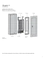
Parts illustration
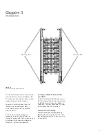
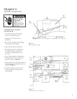
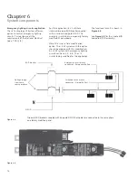
Figure 1.2 below shows the front
view of P1 panel with i-3 Control
Technology V2 components.
Figure 1.2
Panel Overview Diagram
Box (can)
Data rail
BQD breaker
SIPOD
Neutral lugs
Class 2 wire barrier
Neutral extension
Mounting hole (4X)
Location of Main breaker
or main lugs
Ribbon cable
Ground bar
Controller
Note:
Neutral lugs will be covered by the
SIPODs and should not be used (SIPODs
may be added later covering access to the
connections. Connect neutral wires to the
neutral Extensions.
Содержание i-3
Страница 1: ...3 Installation Guide www usa siemens com i 3 i 3 Control Technology V2 ...
Страница 35: ......

