28
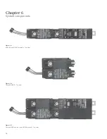
Mounting
screws
“C” Bracket
Mounting
screws
LITTEFUSE: KLKR002
OR EQUIVALENT 600V
2A CLASS “CC ” FUSE
“C” Bracket
LITTEFUSE: KLKR002
OR EQUIVALENT 600V
2A CLASS “CC ” FUSE
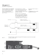
Power
connector
White wire
(neutral)
Green wire
(ground)
Red wire
(power)
Red wire
(power)
Green wire
(ground)
White wire
(neutral)
Chapter 6
System components
Installing the i-3 V2 controller
1. Disconnect and lock off all power
sources supplying this panel.
2. Remove the P1 Panel trim and
deadfront.
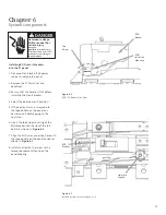
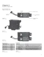
3. Position the controller on the “C”
brackets. (One on each side of
the
panel).
4. Align the controller mounting
bracket holes to the holes on the
“C” bracket as shown in
Figure 6.27
.
5. Install and tighten the screws
(4 total) into the mounting holes as
shown
in
Figure 6.28
to secure the
i-3 V2 controller position.
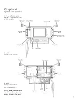
6. Double check that the power wires
are connected as follows:
- White wire to the neutral extension
- Red wire to bus bar on phase A
- Green wire to ground
7. To insure the Controller enclosure is
grounded properly the Controller
mounting brackets shall be connected
to the mounting holes on the P1
panel board chassis by way of (4)
mounting
screws.
Figure 6.27
Installing i-3 V2 Controller Screws
Figure 6.28
Mounting Screws Locations
Figure 6.29
i-3 V2 Controller Connections
Mounting Holes
for Controller
Bracket
DANGER
Hazardous voltage.
Will cause death or
serious injury.
Keep out.
Qualifi ed personnel only.
Disconnect and lock off all
power before working on
this equipment.
Содержание i-3
Страница 1: ...3 Installation Guide www usa siemens com i 3 i 3 Control Technology V2 ...
Страница 35: ......

