background image


4

Chapter 2

Receiving, handling and storage

Receiving

The P1 Lighting Panel with i-3 Control
Technology V2 may be shipped as individual
units. Refer to the shipping slip/bill of lading 
to identify all items included in the shipment.
1. When your shipment arrives, note
  whether the equipment is properly 
  protected from the elements. Also, 
  note the trailer number on which   
  the equipment arrived and blocking 
  of equipment. During unloading 
  make sure the count agrees with 
  the delivery receipt.

2. Make an immediate inspection for
  visible damage upon arrival and prior
  to disturbing or removing packaging
  or protective wrapping. This should be
  done prior to unloading when possible.

  When a total inspection cannot be made  
  prior to unloading, perform a close 
  inspection during unloading. Note 
  visible damage on the delivery receipt.  
  Take pictures when possible.

3. Any visible damage must be noted on
  the delivery receipt and acknowledged
  with the driver’s signature. The damage
  should be described in as much detail
  as possible. It is essential that the 
  notation: “Possible internal damage,  
  subject to inspection” is included on 
  the delivery receipt with damage noted.  
  The consignee or his/her agent should  
  not sign for the shipment.

4. Notify the Siemens sales office 
  immediately of any damage.

5. Arrange for a carrier inspection of 
  damage immediately. IMPORTANT: 
  Do not remove equipment from the 
  location where it was placed when 
  unloading. Be sure this location is 
  properly protected to ensure no further  
  damage will occur. Equipment must be
  inspected by the carrier prior to handling  
  after receipt. This eliminates loss due to  
  possible claims by the carrier that the  
  equipment was damaged or further  
  damaged on-site after unloading.

6. Be sure the equipment is properly
  protected from any further damage 
  by covering it after unloading.

7. If practical, make an additional 
  inspection for concealed damage while  
  carrier inspector is on site. If inspection  
  for concealed damage is not practical
  when the carrier inspector is present, it
  must be done within 15 days of receipt  
  of equipment. If concealed damage is
  found, the carrier must be notified and  
  inspection made prior to taking any 
  corrective action to repair. Also, notify  
  the Siemens sales office immediately.

8. Obtain the original Carrier Inspection
  Report and forward it, along with a
  copy of the noted delivery receipt, to
  the Siemens sales office. Approval must
  be obtained by Siemens from the carrier
  before any repair work can be performed.
  Before approval can be obtained, Siemens  
  must have the documents. The carrier  
  inspection report and/or driver’s 
  signature on the delivery receipt does  
  not constitute approval for repair.

Identification

Individual panels may be identified by 
the rating label showing the panel 
designation information which also 
appears on the shipping list. Refer to the 
general arrangement drawing for location 
of each lighting panel.

Inspection and unpacking

Check the shipping paperwork to ensure
all items have been received. The P1 
Lighting Panel with i-3 Control Technology 
V2 unit should include but is not limited to 
the following items:
•  Panel Enclosure
•  Panel Trim
•  P1 Interior with - Main Device or
  Main Incoming Terminals
•  Circuit numbering (up to 42 
 per 

panel)

•  Mounting and Leveling Kit IMK3
•  Branch Breakers (Note all breakers  
  that will have a SIPOD (see page 25) 
  attached to BQD breakers (20 Amp 
  SIPODs can be attached to 15 Amp 

  or 20 Amp BQDs; while 30 Amp SIPODs 
  can be attached to 15, 20, 25 Amp and 
  30 Amp BQDs).
•  The panel may include up to 18, 30 
  or 42 single pole breakers, or a 
  combination of one, two and three pole  
  breakers up to the number of circuits 
  allowed, depending on the panel size.
  (Three pole breakers can only be used  
  on non controlled circuits; there are no  
  3 pole SIPODs available at this time).
•  Optional emergency control devices:
  Two pole BQD breakers attached to a
  one pole SIPOD combination; up to  
  twelve sets per panel. 
 Notes: 
  1- The maximum number of emergency  
  lights control circuits is limited by the  
  panelboard size: four on 18 circuits 
  panelboard, eight on 30 circuits 
  panelboard;  and 12 on a 42 circuits  
 panelboard.
2- The emergency lighting devices are  
  mounted on factory modified 
  panelboards. This modification may 
  not be done in the field.

i-3 Control Technology V2 components

• SIPODs: up to 18, 30 or 42 one pole
  devices per panel or any combination
  of one pole and two pole BQD breaker/
  SIPOD devices to fill up to 18, 30 or 
   42 circuits.
• One pair of data rails
• One pair of 100% neutral extensions
• One pair of sleeve conduits for low 
  voltage wiring (installer supplied)
• The i-3 V2 Controller
• Power supply (inside the i-3 V2 Controller)
• Controller fuse (inside the i-3 V2
 Controller)
• Controller power switch (inside the i-3  
 V2 

Controller)

• All connectors required in the “Input” 
  section of the controller are shipped  
  plugged in place.

All of the above components are shipped 
fully assembled in the panelboard. If 
there are any shortages or damages not 
previously noted, make certain they are 
noted on the delivery receipt and contact 
the carrier immediately. Also, notify the 
Siemens Sales Office.

Содержание i-3

Страница 1: ...3 Installation Guide www usa siemens com i 3 i 3 Control Technology V2 ...

Страница 2: ...n addition this person has the following qualifications a is trained and authorized to de energize clear ground and tag circuits and equipment in accordance with established safety practices b is trained in the correct care and use of protective equipment such as rubber gloves hard hat safety glasses or face shields flash clothing etc in accordance with established safety practices c is trained in...

Страница 3: ...description 20 Description 21 22 Installing SIPOD into panel 23 Removing SIPOD from panel 24 Data rail 24 Description 24 Removing and installing data rail into panel 25 Neutral extension 26 Description 26 27 i 3 V2 Controller 28 Installing i 3 V2 controller into panel 28 Removing i 3 V2 controller 29 Ribbon Cables 29 Description 29 Ribbon cable connections 30 Appendix 31 A P1 with i 3 Control Tech...

Страница 4: ...nent will be discussed in detail including assembly and removal instructions For additional information contact your Siemens Representative or call Customer Service provided in Appendix D Customer Service Support Information Scope The purpose of this manual is to provide users with a safe and efficient procedure for the installation operation and maintenance of the P1 Series Lighting Panel with i ...

Страница 5: ...iagram Box can Data rail BQD breaker SIPOD Neutral lugs Class 2 wire barrier Neutral extension Mounting hole 4X Location of Main breaker or main lugs Ribbon cable Ground bar Controller Note Neutral lugs will be covered by the SIPODs and should not be used SIPODs may be added later covering access to the connections Connect neutral wires to the neutral Extensions ...

Страница 6: ...carrier before any repair work can be performed Before approval can be obtained Siemens must have the documents The carrier inspection report and or driver s signature on the delivery receipt does not constitute approval for repair Identification Individual panels may be identified by the rating label showing the panel designation information which also appears on the shipping list Refer to the ge...

Страница 7: ...reakers and SIPODs Storage If the P1 Series Lighting Panel with i 3 Control Technology V2 is not installed and energized immediately it should be stored in a clean dry area where a uniform temperature prevents condensation Preferably it should be stored in a heated building with adequate air circulation and protected from dirt and water It should be stored where it is not subject to mechanical dam...

Страница 8: ...bration shock or tilting or other unusual operating conditions For installation replacement of i 3 Control Technology V2 in Siemens P1 panel the following conditions have to be met 1 All branch circuit breakers must be Siemens BQD type breakers one and two poles 15 20 25 and 30 amp 2 The panel gutter has to be clear only wires for electrical loads are allowed in this area 3 No feed through lugs su...

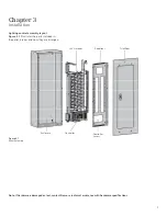
Страница 9: ...ed in the panel interior and how they are arranged Chapter 3 Installation Figure 3 1 Panel Assembly Note If hardware is damaged or lost contact Siemens technical assistance with hardware specifications Trim Door Deadfront i 3 V2 interior Enclosure Controller Controller Access ...

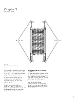
Страница 10: ...nstallation Operation and Maintenance of Panelboards Rated 600 Volts or Less Section 4 P1 interior with i 3 Control Technology V2 installation P1 Interior with i 3 Control Technology V2 are factory assembled Figure 3 3 below shows the interior mounting holes location P1 Chassis Data rail box BQD and SIPOD Neutral extension Figure 3 2 below illustrates i 3 Control Technology V2 Components Ribbon ca...

Страница 11: ...Technology V2 components need to be installed in the panel please refer to the step by step installation instructions described on Chapter 6 System Components Installing additional BQD breaker and SIPOD To install additional BQD breakers and SIPODs please refer to the step by step installation instructions described on Chapter 6 System Components under BQD Breaker and SIPOD sections Location for l...

Страница 12: ...3 System Controller User Guide P N LCIM SYCON 0212 Deadfront installation Prior to completing the installation of panel deadfront and trim carefully review the Inspection section in Chapter 4 Inspection and Testing 1 Be sure the deadfront is installed prior to closing of the panel 2 Be sure all breakers extend properly through the deadfront openings and any provisions or spaces are properly covere...

Страница 13: ...t the user for basic setup information If SIPODs that are installed show as NA on the controller screen then de energize the panel remove the deadfront and check all connections Once all SIPOD modules are connected and operating properly refer to the i 3 V2 System Controller User Guide for further instruction on set up and commissioning 9 In accordance with Section 725 136 of the NEC field install...

Страница 14: ...which are not covered sufficiently for the purchaser s purposes the matter should be referred to the local Siemens sales office Dangerous voltages are present in the equipment which can cause death serious injury or property damage Always disconnect and lock off all power to the equipment before maintenance Maintenance should be performed only by qualified personnel The use of unauthorized parts i...

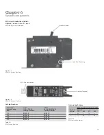
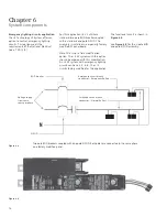
Страница 15: ...Breaker Top View BQD Line Connection Load Lug Terminal RMS Symmetrical Amperes KA Number Volts AC of Poles 120 240 277 480 1 65 14 2 65 14 Interrupting Ratings Table 6 2 BQD Interruption Ratings Continuous 1 Pole 2 Pole Current Rating 120 277V AC 240 480Y 270V AC 40ºC Catalog Number Catalog Number 15A BQD115 BQD215 20A BQD120 BQD220 25A BQD125 BQD225 30A BQD130 BQD230 Catalog Numbers Table 6 1 BQD...

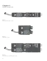
Страница 16: ...14 Chapter 6 System components Figure 6 4 Two pole SIPOD Top View Figure 6 3 BQD 15A and SIPOD Assembly Top View Figure 6 5 Two pole BQD and two pole SIPOD Assembly Top View ...

Страница 17: ...Insert the load side mounting of the BQD breaker into the slot of the top barrier as shown in Figure 6 6 7 Align the BQD line connection hole with the tapped hole on the panel bus bar as shown in Figure 6 7 8 Install and tighten the screw to the torque requirements found on the panel labeling DANGER Hazardous voltage Will cause death or serious injury Keep out Qualified personnel only Disconnect an...

Страница 18: ...ard Note This is not a field modification option The i 3 V2 system with this option should be ordered with this modification An i 3 V2 system with emergency lighting circuits can have 2 4 6 8 10 or 12 circuits factory modified for this application BQD breaker The functional circuit is shown in Figure 6 8 See Figure 6 9 for the 2 pole BQD one pole SIPOD assembly Two pole BDQ breakers coupled with o...

Страница 19: ...arked for the location of emergency lighting circuits controls Figure 6 10 shows the panel deadfront with the labels clearly showing the emergency lighting circuits locations For label 1 see Figure 6 11 for label 2 see Figure 6 12 Label 1 Label 2 Label 2 Top Feed Layout Bottom Feed Layout ...

Страница 20: ...ed to the same source Consult instruction sheet 11 B 1021 01 located in pocket behind door or cover before installation or maintenance For replacement instructions please call the Sales Office at 1 800 427 2256 Siemens Industry Inc Norcross GA 11 C 1050 01 Rev 1 Chapter 6 System components Figure 6 11 Label 1 Figures 6 11 and 6 12 show safety labels used to identify the location of the emergency l...

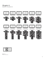
Страница 21: ... BQD SIPOD SIPOD 2 Pole BQD 2 Pole BQD SIPOD SIPOD 2 Pole BQD 2 Pole BQD SIPOD A A C C C C B B B B A A C C B B A A C B SIPOD 2 Pole BQD 2 Pole BQD SIPOD SIPOD 2 Pole BQD 2 Pole BQD SIPOD A B C A phase Key B phase C phase 18 circuit panel with two emergency lights circuits DESIPODMOD1801 18 Circuits overall with 2 Emergency Circuits DESIPODMOD4201 42 Circuits overall with 2 Emergency Circuits DESIP...

Страница 22: ...uit breaker The purpose of a SIPOD is to allow switching of a load ON and OFF from a remote location or according to a pre arranged time schedule The SIPOD will connect to the load side of the breaker using a conductor tab inserted into the breaker load lug The wiring to the loads will be connected to the load lug of the SIPOD which is the same size as the circuit breaker load lug The SIPOD commun...

Страница 23: ...IPOD 2 BQD225 BQD230 Catalog Numbers Table 6 3 SIPOD Catalog Number Table 6 4 SIPOD Components E SIPOD Connector Figure 6 15 SIPOD Side View Components Description A Tang Conductor tab The conductive element that connects the circuit breaker to the SIPOD B Mechanical status Provides the open close status of the SIPOD contacts indicator C Manual closing Allows the customer to close the SIPOD contac...

Страница 24: ...evice as shown in Figure 6 17 The controller must be used to re open the contacts This feature is designed to apply voltage on the circuit prior to commissioning Do not use this feature to open the SIPOD contacts as that will damage the device D SIPOD load lug The SIPOD load lug is identical to the BQD circuit breaker load lug As a result it can receive the same type and size of wire as the circui...

Страница 25: ...d 6 19 Ensure that the SIPOD tang engages into the breaker terminal 7 Tighten the BQD terminal screw to the torque requirements found on the circuit breaker labeling to ensure a proper electrical connection 8 Insert the SIPOD data wire connector into the respective data rail connector as shown in Figure 6 20 The SIPOD data wire connector is equipped with a keying polarized feature which means it c...

Страница 26: ...ending on the size of the panelboard The data rail provides a barrier to isolate the power wiring from the Class 2 signal wiring used to operate the SIPODs Each SIPOD links to the data rail via a 4 wire connector as described in the SIPOD section On the end of the data rail a 26 wire ribbon cable connects the data rail to the printed circuit board There are three available data rail sizes dependin...

Страница 27: ...positioned on the i 3 V2 controller side 4 Loosen the screws 2 total that secure the data rail lid as shown in Figure 6 22 to open the lid for SIPOD and ribbon cable connections 5 Once all connections are properly completed close the data rail lid and tighten the screws Figure 6 22 Opening the Data Rail Lid Loosen the screw to open the lid DANGER Hazardous voltage Will cause death or serious injur...

Страница 28: ...de additional neutral connections when the SIPODs partially cover the normal neutral lugs Each neutral extension provides connections for 18 wires ranging from 6 14 AWG and 3 wires ranging from 1 0 14 AWG 21 connections in total independent of the size of the panel Figure 6 23 Left Neutral Extension for Bottom feed Panel Figure 6 24 Right Neutral Extension for Bottom feed Panel DANGER Hazardous vo...

Страница 29: ...unting bracket Ribbon cable connector Ribbon cable connector Power supplies EIB choke C C only Power switch Fuse Surge protection circuit Chapter 6 System components i 3 V2 controller description Figure 6 25 shows the front view of i 3 V2 controller Figure 6 25 Front View of i 3 V2 Controller For more detailed information about the i 3 V2 Controller configuration and set up procedures please refer...

Страница 30: ... in Figure 6 27 5 Install and tighten the screws 4 total into the mounting holes as shown in Figure 6 28 to secure the i 3 V2 controller position 6 Double check that the power wires are connected as follows White wire to the neutral extension Red wire to bus bar on phase A Green wire to ground 7 To insure the Controller enclosure is grounded properly the Controller mounting brackets shall be conne...

Страница 31: ...ve the i 3 V2 controller Ribbon cables description The ribbon cable is a 26 wire flat connector used to connect the I O Board and the data rail The ribbon cable carries two way data communications between the I O Board and SIPODs including power and ground A pair of ribbon cables is required for each panel one for each side There is a connector on each end of the ribbon cable one for I O Board and...

Страница 32: ...ribbon cable connection to the controller board Figure 6 31 i 3 V2 Controller with Cover Removed Figure 6 32 Ribbon Cable Connection to Data Rail Figure 6 33 Data Rail PCB Note Do not force the ribbon cable connector in the wrong orientation as it could damage the plastic and cause the I O Board to malfunction If the connector does not insert easily check to be sure you are not attempting to conne...

Страница 33: ...Lugs N A Remote Operated Relay Ratings 20 30A Remote Operated Relay Device SIPOD Data Rail 9 15 21 circuits each side Power Supply Ratings 120 277V AC 10 10 Fuse Ratings 2A Class CC Enclosure Heights Inches in 32 38 44 18 30 42 circuits Standard sizes of P1 Panelboards Table A1 panel specifications Appendix A P1 with i 3 Control Technology V2 panel specification The table below lists the specificatio...

Страница 34: ...pport Call us at 1 800 333 7421 or visit www usa siemens com i 3 or e mail ncssc siemens sylvania com For the Nearest Sales Office Call us at 1 800 964 4114 or visit http www3 usa siemens com sales salesoffices html rc 1 For Warranty Support and Customer Service Contact your local sales office or call 1 800 333 7421 For Complete Details on i 3 V2 Controller Configuration Refer to i 3 V2 I O Controller...

Страница 35: ......
Страница 36: ...ions or characteristics of performance which in case of actual use do not always apply as described or which may change as a result of further development of the products An obligation to provide the respective characteristics shall only exist if expressly agreed in the terms of contract All product designations may be trademarks or product names of Siemens AG or supplier companies whose use by th...

Отзывы: