Service Manual
7-329
Operation
Driver Installation
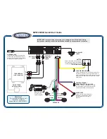
Figure 7-53
Windows XP - Driver location
3.
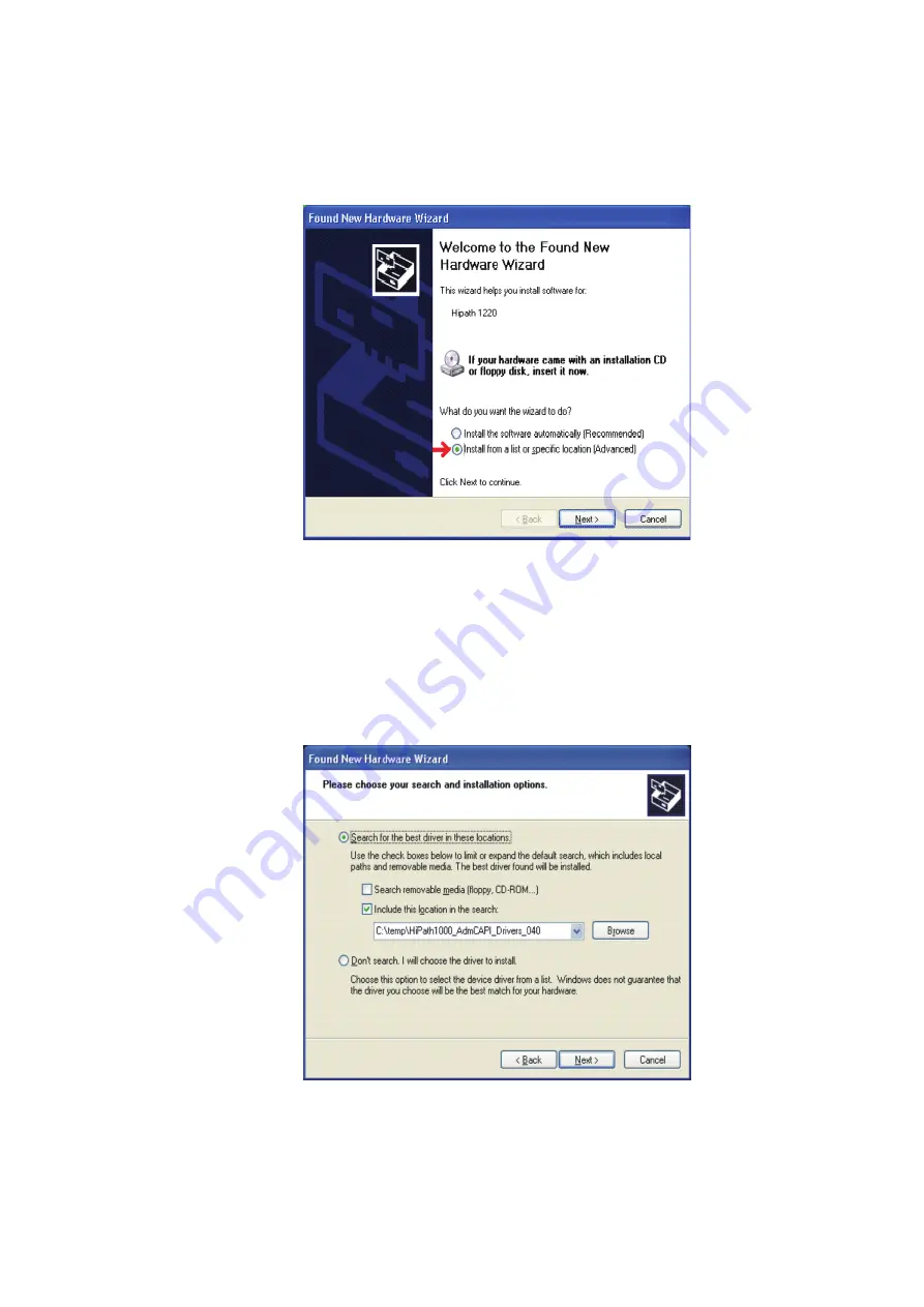
A second window will open. Select “Search for the best CAPI in these locations” then select
“Include this location in the search”. Under Browse, select the directory where the
decompressed driver is stored. Drivers can be found in the \Software\USB Drivers folder
of the CD. The drive is decompressed in C:\Temp (Default). If Admin is selected, use
C:TempoptiPoint_Adm_Drivers_039 directory. If Admin + CAPI is selected, use
CTempoptiPoint_AdmCAPI_ Drivers_039. Select a folder and click "Next"
Figure 7-54
Windows XP - Driver location
Содержание HiPath 1100
Страница 1: ...HiPath 1100 HiPath 1120 HiPath 1150 HiPath 1190 Service Manual ...
Страница 14: ...Figures 14 Service Manual ...
Страница 124: ...Modules 3 124 Service Manual Interconnect cables ...
Страница 162: ...Installation 4 162 Service Manual Installing modules Figure 4 31 Installing a Music module HiPath 1120 ...
Страница 190: ...Installation 4 190 Service Manual Performing a visual inspection ...
Страница 323: ...Service Manual 7 323 Operation Driver Installation Figure 7 44 Windows 2000 Driver location ...
Страница 368: ...Operation 7 368 Service Manual HiPath 1100 applications ...
Страница 384: ...Abbreviations 9 384 Service Manual ...
Страница 388: ...388 Service Manual ...