Chapter 6 - 7SR157 Commissioning and Maintenance Guide
Chapter 6 - Page 7 of 14
©2016 Siemens Protection Devices Limited
Section 2:
Control Functions
2.1
Phase Angle Tests
The Phase Angle detector algorithm, which is used for both Check and System Sync elements, is best tested
using a portable relay test set.
Disable
25 System Sync
. Enable
25 Check Sync
and set the
25 Check Sync Angle
to a practical value such as
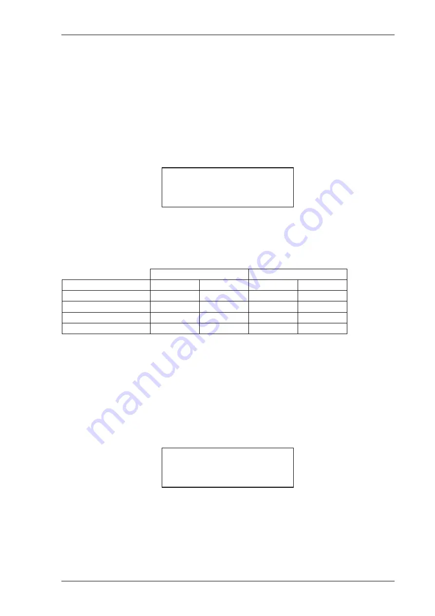
20°. Apply nominal volts to both the Line and Bus input terminals of the relay and adjust the phase angle between
the two voltages to a value greater than
25 Check Sync Angle
. Using the INSTRUMENTS MODE \ SYNC
METERS, scroll down to the Phase screen display:
Slowly decrease the phase angle difference between the Line and Bus voltages and note the value where Phase
displays CS In; this is the pick-up value. Slowly increase the phase angle difference and check the drop-off value
where Phase displays CS Out. Record the values in the table below. Repeat this test having effectively reversed
the angles between Line and Bus.
The results should fall within the claims made in the relevant sections of: Chapter 3 - Performance Specification.
Positive angle
Negative angle
25 Check Sync Angle (°)
Pick Up (°)
Drop Off (°)
Pick Up (°)
Drop Off (°)
2.2
Slip Frequency Tests
The Slip Frequency detector algorithm, which is used for both Check and System Sync elements, is more difficult
to test as it requires variable frequency sources. A portable relay test set with fixed and variable frequency voltage
source output is essential for this.
Disable
25 System Sync
and
25 System Split Detector
. Enable both the
25 Check Sync
and
25 Check Sync
Slip Freq
functions. Set
25 Check Sync Slip
to a practical value such as 0.05Hz. Apply nominal volts to both the
Line and Bus input terminals of the relay, and adjust the frequency difference between the two to a value greater
than the
25 Check Sync Slip
setting value. Using the INSTRUMENTS MODE \ SYNC METERS, scroll down to
the Slip screen display:
Slowly reduce the frequency difference until the element picks up. Slip should now display CS In. Gradually
increase the slip until the element drops off as indicated by CS Out. Repeat this test having effectively reversed
the direction of slip between Line and Bus.
The results should fall within the claims made in the relevant sections of: Chapter 3 - Performance Specification.
Slip
-------------------------------------------------
CS OUT
Phase
-------------------------------------------------
CS OUT
Содержание 7SR157 Argus
Страница 1: ...Energy Management 7SR157 Argus Check and System Synchronising Relay Reyrolle Protection Devices ...
Страница 2: ......
Страница 4: ...7SR157 Contents ...
Страница 58: ...7SR158 Technical Manual Chapter 3 Page 2 of 18 2022 Siemens Protection Devices Limited ...
Страница 76: ...7SR157 Technical Manual Chapter 4 Page 2 of 58 2016 Siemens Protection Devices Limited ...
Страница 80: ...7SR157 Technical Manual Chapter 4 Page 6 of 58 2016 Siemens Protection Devices Limited ...
Страница 92: ...7SR157 Technical Manual Chapter 4 Page 18 of 58 2016 Siemens Protection Devices Limited ...
Страница 122: ...7SR157 Technical Manual Chapter 4 Page 48 of 58 2016 Siemens Protection Devices Limited ...
Страница 124: ...7SR157 Technical Manual Chapter 4 Page 50 of 58 2016 Siemens Protection Devices Limited ...
Страница 126: ...7SR157 Technical Manual Chapter 4 Page 52 of 58 2016 Siemens Protection Devices Limited ...
Страница 150: ...7SR157 Technical Manual Chapter 5 Page 18 of 18 2018 Siemens Protection Devices Limited ...
Страница 161: ...Chapter 6 7SR157 Commissioning and Maintenance Guide Chapter 6 Page 11 of 14 2016 Siemens Protection Devices Limited ...
Страница 179: ...Siemens Protection Devices 1 ...


