


The following measured values are available in the order specified:
Table B-1
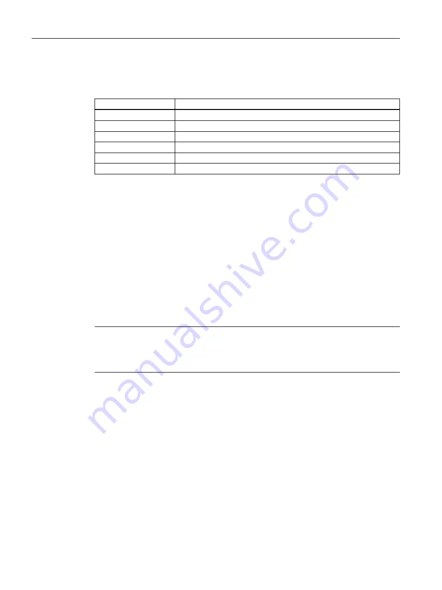
Cyclic data transmission, measured values
Slot No.
Parameter / measured value
1
Flow (volume or mass flow)
2
Sound velocity
3
Quantity (volume or mass) net
4
Ultrasonic amplitude
5
Quantity (volume or mass) forward
6
Quantity (volume or mass) reverse
Output data are sent to the device together with the cyclic request telegram. The number and
type of actually transferred data can be determined with the aid of the configuration data (see
GSD files (Page 98)).
B.2
Acyclic Data Transmission
The acyclic data transmission is mainly used for remote control of devices, i.e. for transmitting
parameters during commissioning, maintenance, batch processes or for displaying variables
which are not included in the cyclic process data traffic.
Acyclic accesses can be carried out by Master class 1 (C1 connection) or Master class 2 (C2
connection). SITRANS FUS060 PROFIBUS PA supports up to 4 simultaneous C2 connections.
The approximately 400 parameters including address (slot and index), format, value range, start
value and attributes are stored in an object list "Obj8159.rtf" which will be provided on request.
Note
Acyclic operation with SIMATIC PDM
We recommend using the SIMATIC PDM software package and a PC (compatible with industry
standard) or a programming unit for acyclic operation.
B.3
Input Data (from Slave to Master)
Input data are process data (measured values) which are transmitted from the device to the
master in the following format:
Every measured value consists of 5 bytes which are composed of a floating point value
corresponding with IEEE - 754 (4 bytes) and the correspondent measured value status (1 byte).
PROFIBUS communication
B.3 Input Data (from Slave to Master)
SITRANS FUS060 with PROFIBUS PA
90
Operating Instructions, 09/2021, A5E02225054-AD