Technical specifications
7.3 Interface description
Carrier controller
Operating Instructions, 09/2013, A5E03474162-02
43
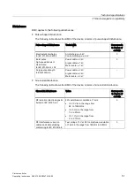
Insulation strength
Insulation strength to ground was proven in a type test at the following test voltage to
IEC 61131-2:
Applies to
Circuits with rated voltage of V
in
to
other circuits or ground
Test voltage
Line voltage connection –X2
Geared motor connection –X1
Braking resistor connection –
X3
AC line voltage ≥ 230 V
500 V DC
test time 5 s,
insulation resistance 1 M
Ω
Protection class and degree of protection
Characteristic
Standard
Classification
Protection class
EN 61131-2
Protection class I
Degree of protection
EN 60529
IP65
The information for protection class and degree of protection are only effective once the
interfaces of the carrier controller are covered with a matching connector or other suitable
means.
Cable lengths and cable specifications
Connection between
Cable length Specification
Carrier controller – EMS rail, L1, L2,
L3, PE
< 2 m
≥ 2.5 mm²; recommended
Carrier controller – EMS rail, RAIL A
and RAIL B
< 2 m
≥ 2.5mm²; recommended
Carrier controller – geared motor
< 5 m 4 × 2.5 mm² for U, V, W, PE, shielded
2 × 0.75 mm² for motor holding brake
and temperature monitoring
Carrier controller – braking resistor
< 10 m
≥ 1.5 mm², AWG 16
Carrier controller – sensor
< 2 m
≥ 0.35 mm², AWG 22
Carrier controller – programming
device
< 2 m Ethernet patch cable, Cat. 5

